NAVIGATION SYSTEM, Diagnostic DTC:B15D0

| DTC Code | DTC Name |
|---|---|
| B15D0 | MOST Communication Malfunction |
DESCRIPTION
This DTC is stored when the MOST network cannot be established after the master unit is activated.
| DTC No. | DTC Detection Condition | Trouble Area |
|---|---|---|
| B15D0 | MOST network cannot be established. |
|
-
*1: w/ Rear Seat Entertainment System
Tech Tips
-
For the MOST network, the multi-media module receiver assembly is the master unit.
-
Errors may occur in MOST communication between devices due to problems such as electrical noise.
WIRING DIAGRAM
-
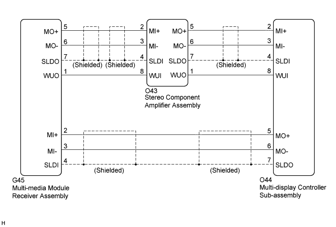
w/ Rear Seat Entertainment System
-
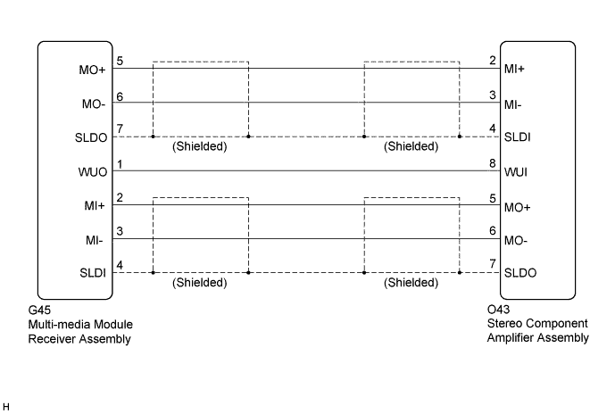
w/o Rear Seat Entertainment System
INSPECTION PROCEDURE
Note
-
When replacing the multi-media module receiver assembly or telematics transceiver, perform vehicle contract setting (w/ Telematics Transceiver) Click here.
-
When replacing the multi-media module receiver assembly, perform vehicle contract setting (w/o Telematics Transceiver) Click here.
w/ G-BOOK System:
PROCEDURE
-
CHECK DTC
-
If DTC B15C3 is output, perform the troubleshooting of DTC B15C3 first.
Result Result Proceed to DTC B15C3 is not output. A DTC B15C3 is output. B
B 
GO TO DTC "B15C3" IN DIAGNOSTIC TROUBLE CODE CHART Click here
A 
-
-
PERFORM MOST LINE CHECK
-
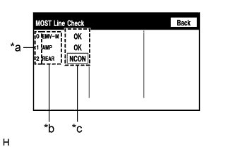
Text in Illustration *a Node position number for devices that use MOST communication *b Device name *c Result Display the "MOST Line Check" screen.
-
Check the result on the "MOST Line Check" screen.
Result Result Proceed to "NCON" is displayed for "AMP". A "NCON" is displayed for "REAR" (w/ Rear Seat Entertainment System). B "OK" is displayed for all items. C Tech Tips
-
When "NCON" is displayed for more than 1 item, proceed to the step for the device that has the smallest node position number.
-
The "MOST Line Check" screen can be displayed only when DTC B15D0 is stored.
-
B 
CHECK MOST COMMUNICATION CONNECTORS Click here
C
CHECK HARNESS AND CONNECTOR (MULTI-MEDIA MODULE RECEIVER ASSEMBLY - STEREO COMPONENT AMPLIFIER ASSEMBLY) Click here
A
-
-
CHECK MOST COMMUNICATION CONNECTORS
-
Check the MOST communication line connectors.
-
Check if the MOST communication line connector between the multi-media module receiver assembly and stereo component amplifier assembly has any connection problems Click here.
-
-
Display the "MOST Line Check" screen and check the result Click here.
Result Result Proceed to "NCON" is displayed for "AMP". A The screen cannot be changed to the "MOST Line Check" screen. B Tech Tips
When the malfunction in the MOST network is repaired, the screen cannot be changed to the "MOST Line Check" screen.
B
END
A
-
-
CHECK HARNESS AND CONNECTOR (WAKE-UP SIGNAL)
-
Disconnect the O43 stereo component amplifier assembly connector.
-
Measure the voltage according to the value(s) in the table below.
Standard Voltage Tester Connection Condition Specified Condition O43-8 (WUI) - Body ground Power switch on (ACC) 4.5 V or higher
NG
CHECK HARNESS AND CONNECTOR (STEREO COMPONENT AMPLIFIER ASSEMBLY - MULTI-DISPLAY CONTROLLER SUB-ASSEMBLY) Click here
OK 
REPLACE STEREO COMPONENT AMPLIFIER ASSEMBLY Click here
-
-
CHECK HARNESS AND CONNECTOR (STEREO COMPONENT AMPLIFIER ASSEMBLY - MULTI-DISPLAY CONTROLLER SUB-ASSEMBLY)
-
Disconnect the O43 stereo component amplifier assembly connector.
-
Disconnect the G45 multi-media module receiver assembly connector.
-
Measure the resistance according to the value(s) in the table below.
Standard Resistance Tester Connection Condition Specified Condition O43-8 (WUI) - G45-1 (WUO) Always Below 1 Ω O43-8 (WUI) - Body ground Always 10 kΩ or higher
NG
REPAIR OR REPLACE HARNESS OR CONNECTOR
OK
REPLACE MULTI-MEDIA MODULE RECEIVER ASSEMBLY Click here
-
-
CHECK MOST COMMUNICATION CONNECTORS
-
Check the MOST communication line connectors.
-
Check if the MOST communication line connector between the multi-display controller sub-assembly and stereo component amplifier assembly has any connection problems Click here.
-
-
Display the "MOST Line Check" screen and check the result Click here.
Result Result Proceed to "NCON" is displayed for "REAR". A The screen cannot be changed to the "MOST Line Check" screen. B Tech Tips
When the malfunction in the MOST network is repaired, the screen cannot be changed to the "MOST Line Check" screen.
B
END
A
-
-
CHECK HARNESS AND CONNECTOR (WAKE-UP SIGNAL)
-
Disconnect the O44 multi-display controller sub-assembly connector.
-
Measure the voltage according to the value(s) in the table below.
Standard Voltage Tester Connection Condition Specified Condition O44-8 (WUI) - Body ground Power switch on (ACC) 4.5 V or higher
NG
CHECK HARNESS AND CONNECTOR (MULTI-DISPLAY CONTROLLER SUB-ASSEMBLY - STEREO COMPONENT AMPLIFIER ASSEMBLY) Click here
OK
REPLACE MULTI-DISPLAY CONTROLLER SUB-ASSEMBLY Click here
-
-
CHECK HARNESS AND CONNECTOR (MULTI-DISPLAY CONTROLLER SUB-ASSEMBLY - STEREO COMPONENT AMPLIFIER ASSEMBLY)
-
Disconnect the O44 multi-display controller sub-assembly connector.
-
Disconnect the O43 stereo component amplifier assembly connector.
-
Measure the resistance according to the value(s) in the table below.
Standard Resistance Tester Connection Condition Specified Condition O44-8 (WUI) - O43-1 (WUO) Always Below 1 Ω O44-8 (WUI) - Body ground Always 10 kΩ or higher
NG
REPAIR OR REPLACE HARNESS OR CONNECTOR
OK
REPLACE STEREO COMPONENT AMPLIFIER ASSEMBLY Click here
-
-
CHECK HARNESS AND CONNECTOR (MULTI-MEDIA MODULE RECEIVER ASSEMBLY - STEREO COMPONENT AMPLIFIER ASSEMBLY)
-
Disconnect the G45 multi-media module receiver assembly connector.
-
Disconnect the O43 stereo component amplifier assembly connector.
-
Measure the resistance according to the value(s) in the table below.
Standard Resistance Tester Connection Condition Specified Condition G45-5 (MO+) - O43-2 (MI+) Always Below 1 Ω G45-6 (MO-) - O43-3 (MI-) Always Below 1 Ω G45-7 (SLDO) - O43-4 (SLDI) Always Below 1 Ω G45-1 (WUO) - O43-8 (WUI) Always Below 1 Ω G45-5 (MO+) - Body ground Always 10 kΩ or higher G45-6 (MO-) - Body ground Always 10 kΩ or higher G45-7 (SLDO) - Body ground Always 10 kΩ or higher G45-1 (WUO) - Body ground Always 10 kΩ or higher -
Proceed to the next step based on the inspection result.
Result Condition Proceed to OK (w/o Rear Seat Entertainment System) A OK (w/ Rear Seat Entertainment System) B NG C
B
CHECK HARNESS AND CONNECTOR (STEREO COMPONENT AMPLIFIER ASSEMBLY - MULTI-DISPLAY CONTROLLER SUB-ASSEMBLY) Click here
C
REPAIR OR REPLACE HARNESS OR CONNECTOR
A
-
-
CHECK HARNESS AND CONNECTOR (MULTI-MEDIA MODULE RECEIVER ASSEMBLY - STEREO COMPONENT AMPLIFIER ASSEMBLY)
-
Disconnect the O43 stereo component amplifier assembly connector.
-
Disconnect the G45 multi-media module receiver assembly connector.
-
Measure the resistance according to the value(s) in the table below.
Standard Resistance Tester Connection Condition Specified Condition O43-5 (MO+) - G45-2 (MI+) Always Below 1 Ω O43-6 (MO-) - G45-3 (MI-) Always Below 1 Ω O43-7 (SLDO) - G45-4 (SLDI) Always Below 1 Ω O43-5 (MO+) - Body ground Always 10 kΩ or higher O43-6 (MO-) - Body ground Always 10 kΩ or higher O43-7 (SLDO) - Body ground Always 10 kΩ or higher -
Proceed to the next step based on the inspection result.
Result Condition Proceed to NG A OK B
B
REPLACE STEREO COMPONENT AMPLIFIER ASSEMBLY Click here
A
REPAIR OR REPLACE HARNESS OR CONNECTOR
-
-
CHECK HARNESS AND CONNECTOR (STEREO COMPONENT AMPLIFIER ASSEMBLY - MULTI-DISPLAY CONTROLLER SUB-ASSEMBLY)
-
Disconnect the O43 stereo component amplifier assembly connector.
-
Disconnect the O44 multi-display controller sub-assembly connector.
-
Measure the resistance according to the value(s) in the table below.
Standard Resistance Tester Connection Condition Specified Condition O43-5 (MO+) - O44-2 (MI+) Always Below 1 Ω O43-6 (MO-) - O44-3 (MI-) Always Below 1 Ω O43-7 (SLDO) - O44-4 (SLDI) Always Below 1 Ω O43-1 (WUO) - O44-8 (WUI) Always Below 1 Ω O43-5 (MO+) - Body ground Always 10 kΩ or higher O43-6 (MO-) - Body ground Always 10 kΩ or higher O43-7 (SLDO) - Body ground Always 10 kΩ or higher O43-1 (WUO) - Body ground Always 10 kΩ or higher
NG
REPAIR OR REPLACE HARNESS OR CONNECTOR
OK
-
-
CHECK HARNESS AND CONNECTOR (MULTI-MEDIA MODULE RECEIVER ASSEMBLY - MULTI-DISPLAY CONTROLLER SUB-ASSEMBLY)
-
Disconnect the G45 multi-media module receiver assembly connector.
-
Disconnect the O44 multi-display controller sub-assembly connector.
-
Measure the resistance according to the value(s) in the table below.
Standard Resistance Tester Connection Condition Specified Condition O44-5 (MO+) - G45-2 (MI+) Always Below 1 Ω O44-6 (MO-) - G45-3 (MI-) Always Below 1 Ω O44-7 (SLDO) - G45-4 (SLDI) Always Below 1 Ω O44-5 (MO+) - Body ground Always 10 kΩ or higher O44-6 (MO-) - Body ground Always 10 kΩ or higher O44-7 (SLDO) - Body ground Always 10 kΩ or higher
NG
REPAIR OR REPLACE HARNESS OR CONNECTOR
OK
-
-
REPLACE MULTI-DISPLAY CONTROLLER SUB-ASSEMBLY
-
Replace the multi-display controller sub-assembly Click here.
-
Clear the DTCs Click here.
-
Recheck for DTCs and check that no DTCs are output.
OK No DTCs are output.
NG
REPLACE STEREO COMPONENT AMPLIFIER ASSEMBLY Click here
OK
END
-
-
REPLACE STEREO COMPONENT AMPLIFIER ASSEMBLY
-
Replace the stereo component amplifier assembly Click here.
-
Clear the DTCs Click here.
-
Recheck for DTCs and check that no DTCs are output.
OK No DTCs are output.
NG
REPLACE MULTI-MEDIA MODULE RECEIVER ASSEMBLY Click here
OK
END
-