AUDIO AND VISUAL SYSTEM (w/o Multi-display) Cellular Phone Voice Circuit between Radio Receiver and Stereo Component Amplifier
DESCRIPTION
This circuit is used when an incoming cellular phone voice in the "Bluetooth" handsfree system is received.
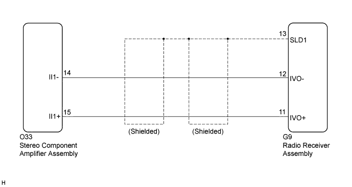
WIRING DIAGRAM
INSPECTION PROCEDURE
PROCEDURE
-
CHECK HARNESS AND CONNECTOR (RADIO RECEIVER ASSEMBLY - STEREO COMPONENT AMPLIFIER ASSEMBLY)
-
Disconnect the G9 radio receiver assembly connector.
-
Disconnect the O33 stereo component amplifier assembly connector.
-
Measure the resistance according to the value(s) in the table below.
Standard Resistance Tester Connection Condition Specified Condition G9-11 (IVO+) - O33-15 (II1+) Always Below 1 Ω G9-12 (IVO-) - O33-14 (II1-) Always Below 1 Ω G9-11 (IVO+) - Body ground Always 10 kΩ or higher G9-12 (IVO-) - Body ground Always 10 kΩ or higher G9-13 (SLD1) - Body ground Always 10 kΩ or higher
NG 
REPAIR OR REPLACE HARNESS OR CONNECTOR
OK 
PROCEED TO NEXT SUSPECTED AREA SHOWN IN PROBLEM SYMPTOMS TABLE Click here
-