AUDIO AND VISUAL SYSTEM (w/ Multi-display) AVC-LAN Circuit
DESCRIPTION
Each unit of the audio and visual system connected to the AVC-LAN (communication bus) transfers the switch signals using the AVC-LAN.
If a short to +B or short to ground occurs in the AVC-LAN, the audio and visual system will not function normally because communication is not possible.
WIRING DIAGRAM
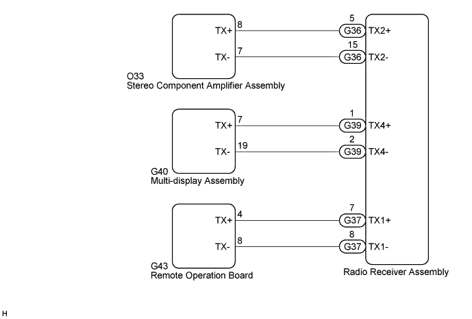
INSPECTION PROCEDURE
Tech Tips
The radio receiver assembly is the master unit.
PROCEDURE
-
INSPECT RADIO RECEIVER ASSEMBLY
-
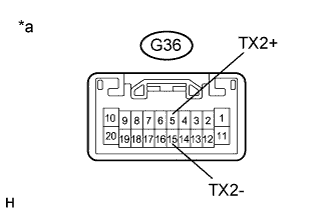
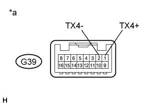
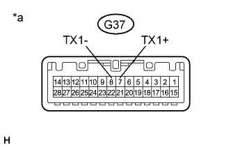
Disconnect the G36, G37 and G39 radio receiver assembly connectors.
-
Measure the resistance according to the value(s) in the table below.
Standard Resistance Tester Connection Condition Specified Condition G36-5 (TX2+) - G36-15 (TX2-) Always 60 to 80 Ω G39-1 (TX4+) - G39-2 (TX4-) Always 60 to 80 Ω G37-7 (TX1+) - G37-8 (TX1-) Always 60 to 80 Ω Text in Illustration *a Component without harness connected
(Radio Receiver Assembly)
NG 
REPLACE RADIO RECEIVER ASSEMBLY Click here
OK 
-
-
CHECK HARNESS AND CONNECTOR (AVC-LAN CIRCUIT)
-
Disconnect the G36, G37 and G39 radio receiver assembly connectors.
-
Disconnect the O33 stereo component amplifier assembly connector.
-
Disconnect the G40 multi-display assembly connector.
-
Disconnect the G43 remote operation board connector.
-
Measure the resistance according to the value(s) in the table below.
Standard Resistance Tester Connection Condition Specified Condition G36-5 (TX2+) - O33-8 (TX+) Always Below 1 Ω G36-15 (TX2-) - O33-7 (TX-) Always Below 1 Ω G39-1 (TX4+) - G40-7 (TX+) Always Below 1 Ω G39-2 (TX4-) - G40-19 (TX-) Always Below 1 Ω G37-7 (TX1+) - G43-4 (TX+) Always Below 1 Ω G37-8 (TX1-) - G43-8 (TX-) Always Below 1 Ω G36-5 (TX2+) - Body ground Always 10 kΩ or higher G36-15 (TX2-) - Body ground Always 10 kΩ or higher G39-1 (TX4+) - Body ground Always 10 kΩ or higher G39-2 (TX4-) - Body ground Always 10 kΩ or higher G37-7 (TX1+) - Body ground Always 10 kΩ or higher G37-8 (TX1-) - Body ground Always 10 kΩ or higher
NG
REPAIR OR REPLACE HARNESS OR CONNECTOR
OK
-
-
INSPECT MALFUNCTIONING PARTS
-
Disconnect and reconnect each slave unit one by one until the master unit returns to normal operation.
Tech Tips
-
Check all slave units.
-
If disconnecting a slave unit causes the master unit to return to normal operation, the slave unit is defective and should be replaced.
OK Master unit returns to normal operation. -
NG
REPLACE RADIO RECEIVER ASSEMBLY Click here
OK 
REPLACE MALFUNCTIONING PARTS
-