AUDIO AND VISUAL SYSTEM (w/ Multi-display), Diagnostic DTC:B1575

| DTC Code | DTC Name |
|---|---|
| B1575 | GVIF Disconnected (from EMV/MM Integrated Device to Multi Display) |
DESCRIPTION
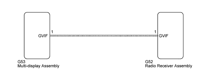
The radio receiver assembly and multi-display assembly are connected via video signal (digital) lines.
This DTC is stored when a video signal (digital) line is disconnected.
| DTC No. | DTC Detection Condition | Trouble Area |
|---|---|---|
| B1575 | Video signal (digital) is lost. |
|
WIRING DIAGRAM
INSPECTION PROCEDURE
PROCEDURE
-
REPLACE HARNESS AND CONNECTOR (RADIO RECEIVER ASSEMBLY - MULTI-DISPLAY ASSEMBLY)
-
Replace the harness and connector.
-
Clear the DTCs Click here.
-
Recheck for DTCs and check that no DTCs are output.
OK No DTCs are output.
NG 
REPLACE MULTI-DISPLAY ASSEMBLY Click here
OK 
END
-
-
REPLACE MULTI-DISPLAY ASSEMBLY
-
Replace the multi-display assembly Click here.
-
Clear the DTCs Click here.
-
Recheck for DTCs and check that no DTCs are output.
OK No DTCs are output.
NG 
REPLACE RADIO RECEIVER ASSEMBLY Click here
OK
END
-