-
Do not replace the spiral cable with the auxiliary battery connected and the power switch on (IG).
-
Do not rotate the spiral cable without the steering wheel with the auxiliary battery connected and the power switch on (IG).
-
Ensure that the steering wheel is installed and aligned straight when inspecting the steering sensor.
-
Do not remove the steering sensor from the spiral cable.
- Click here
INSTALL STEERING INTERMEDIATE SHAFT ASSEMBLY
-
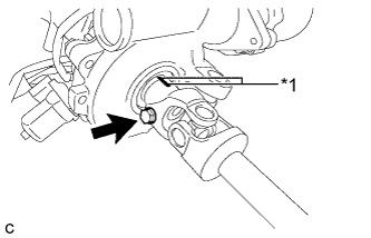
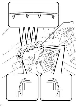
Align the matchmarks on the steering intermediate shaft assembly and steering column assembly.
Table 1. Text in Illustration *1 Matchmark -
Install the bolt.
35 N*m 360 kgf*cm 26 ft.*lbf
-
- Click here
INSTALL STEERING POST ASSEMBLY
-
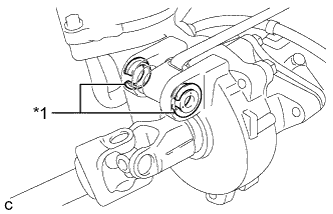
Check that the 2 bushings are securely installed to the steering column assembly.
Table 2. Text in Illustration *1 Bushing Tip:If the bushings are missing or damaged, replace the steering column assembly with a new one.
-
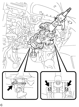
Install the steering post assembly with the bolt and 2 nuts.
Bolt 36 N*m 367 kgf*cm 27 ft.*lbf Nut 25 N*m 255 kgf*cm 18 ft.*lbf -
Engage the 2 wire harness clamps.
-
Connect the connectors and engage the wire harness clamps to the steering post assembly.
-
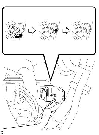
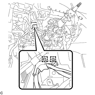
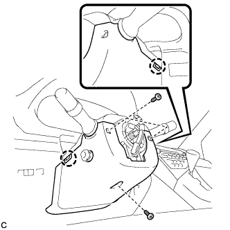
Connect the connector to the power steering ECU assembly.
Tip:As shown in the illustration, securely return the lock lever to its original position to connect the connector.
-
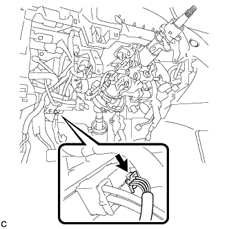
Connect the connector to the power steering ECU assembly.
-
- Click here
CONNECT STEERING INTERMEDIATE SHAFT ASSEMBLY
-
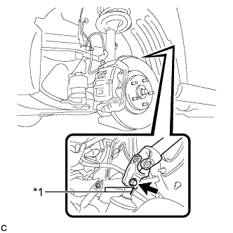
Align the matchmarks on the steering intermediate shaft assembly and power steering link assembly.
Table 3. Text in Illustration *1 Matchmark -
Install the bolt.
35 N*m 360 kgf*cm 26 ft.*lbf -
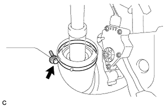
Install the steering intermediate shaft assembly to the steering column hole shield.
-
Tighten the bolt.
-
- Click here
ALIGN FRONT WHEELS FACING STRAIGHT AHEAD
- Click here
INSTALL TURN SIGNAL SWITCH ASSEMBLY WITH SPIRAL CABLE SUB-ASSEMBLY
-
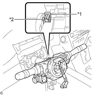
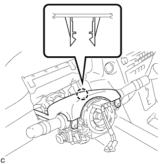
Using pliers, expand the clamp.
Table 4. Text in Illustration *1 Clamp *2 Claw -
While holding the clamp expanded, install the turn signal switch assembly with spiral cable sub-assembly to the steering column assembly and engage the claw.
-
Return the clamp to its original position.
-
Connect the connectors to the turn signal switch assembly with spiral cable sub-assembly.
-
- Click here
INSTALL STEERING COLUMN COVER
-
Engage the claw to install the upper steering column cover.
-
Engage the 2 claws to install the lower steering column cover to the upper steering column cover.
Note:Do not damage the tilt and telescopic switch.
-
Install the 3 screws.
2.0 N*m 20 kgf*cm 18 in.*lbf -
Engage the 4 clips and 2 guides to install the instrument panel cluster finish panel to the upper steering column cover.
Table 5. Text in Illustration *1 Instrument Panel Cluster Finish Panel
-
- Click here
INSTALL BRAKE PEDAL SUPPORT ASSEMBLY (for LHD)
Tip:Refer to the instructions for Installation of the brake pedal support assembly (Click here).
- Click here
INSTALL BRAKE PEDAL SUPPORT ASSEMBLY (for RHD)
Tip:Refer to the instructions for Installation of the brake pedal support assembly (Click here).
- Click here
ALIGN FRONT WHEELS FACING STRAIGHT AHEAD
- Click here
ADJUST SPIRAL CABLE WITH SENSOR SUB-ASSEMBLY
-
Check that the power switch is off.
-
Check that the cable is disconnected from the negative (-) auxiliary battery terminal.
CAUTION:Wait at least 90 seconds after disconnecting the cable from the negative (-) auxiliary battery terminal to disable the SRS system.
-
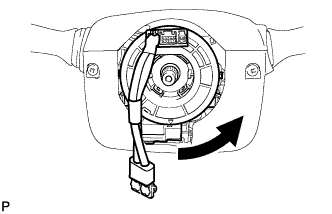
Rotate the spiral cable counterclockwise slowly by hand until it stops.
Note:Do not turn the spiral cable using the airbag wire harness.
-
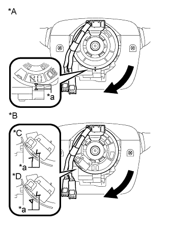
Rotate the spiral cable clockwise approximately 2.5 turns to align the marks.
Table 6. Text in Illustration *A w/o Steering Heater *B w/ Steering Heater *C Type A *D Type B *a Alignment Mark Note:Do not turn the spiral cable using the airbag wire harness.
Tip:The spiral cable will rotate approximately 2.5 turns to both the left and right from the center.
-
- Click here
INSTALL STEERING WHEEL ASSEMBLY
-
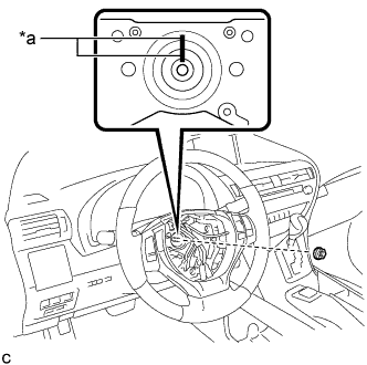
Install the steering wheel assembly aligning the matchmarks on the steering wheel assembly and steering main shaft.
Table 7. Text in Illustration *a Matchmark -
Install the steering wheel assembly set nut.
50 N*m 510 kgf*cm 37 ft.*lbf -
w/ Steering Heater:
-
Connect the connector.
-
-
Connect each connector to the spiral cable.
-
- Click here
INSTALL STEERING PAD
Tip:Refer to the instructions for Installation of the steering pad (Click here).
- Click here
INSTALL FRONT WHEEL LH
103 N*m 1050 kgf*cm 76 ft.*lbf - Click here
ALIGN FRONT WHEELS FACING STRAIGHT AHEAD
- Click here
CONNECT CABLE TO NEGATIVE BATTERY TERMINAL
Note:
-
Make sure that the cable has been disconnected from the battery terminal for at least 2 seconds before reconnecting the cable.
-
Connect the cable to the negative (-) battery terminal with the front wheels facing straight ahead.
-
Reset the auto away/return function setting to the previous condition by changing the customize parameter (Click here).
-
When disconnecting the cable, some systems need to be initialized after the cable is reconnected (Click here).
-
- Click here
INSTALL REAR DECK FLOOR BOX
-
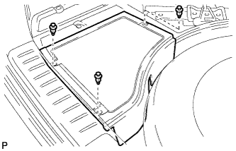
Install the rear deck floor box with the 3 clips.
-
- Click here
INSPECT STEERING PAD
-
Make sure that the horn sounds.
Tip:If the horn does not sound, inspect the horn system (Click here).
-
- Click here
PERFORM DIAGNOSTIC SYSTEM CHECK
- Click here
INSPECT SRS WARNING LIGHT
-
Inspect the SRS warning light (Click here).
-