Some of these service operations affect the SRS airbag system. Read the precautionary notices concerning the SRS airbag system before servicing (Click here).
-
Do not replace the spiral cable with the auxiliary battery connected and the power switch on (IG).
-
Do not rotate the spiral cable without the steering wheel with the auxiliary battery connected and the power switch on (IG).
-
Ensure that the steering wheel is installed and aligned straight when inspecting the steering sensor.
-
Do not remove the steering sensor from the spiral cable.
- Click here
PRECAUTION (w/ Navigation System for HDD)
Note:After the power switch is turned off, the display and navigation module display (HDD navigation system) records various types of memory and settings. As a result, after turning the power switch off, make sure to wait for the time specified in the following table before disconnecting the cable from the negative (-) battery terminal.
Table 1. Waiting Time before Disconnecting Cable from Negative (-) Battery Terminal Specification Waiting Time w/o Telematics transceiver 60 sec. w/ Telematics transceiver 120 sec. - Click here
PRECAUTION (w/ Air Suspension)
Note:Be sure to read Precaution thoroughly before servicing (Click here).
- Click here
PRECAUTION
Note:Be sure to read Precaution thoroughly before servicing (Click here).
- Click here
ALIGN FRONT WHEELS FACING STRAIGHT AHEAD
- Click here
REMOVE REAR DECK FLOOR BOX
-
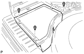
Remove the 3 clips and the rear deck floor box.
-
- Click here
DISCONNECT CABLE FROM NEGATIVE BATTERY TERMINAL
-
Disable the auto away/return function by changing the customize parameter (Click here).
Note:Record the current customize parameter setting (whether the auto away/return function is enabled or disabled) in order to restore the current setting after finishing this operation.
Tip:Performing the above operation disables the auto away/return function when the power switch is turned off.
-
Turn the power switch on (IG). Operate the tilt and telescopic switch to fully extend and lower the steering column assembly.
-
Turn the power switch off and disconnect the cable from the negative (-) battery terminal.
CAUTION:Wait at least 90 seconds after disconnecting the cable from the negative (-) battery terminal to disable the SRS system.
Note:When disconnecting the cable, some systems need to be initialized after the cable is reconnected (Click here).
-
- Click here
REMOVE FRONT WHEEL LH
- Click here
REMOVE STEERING PAD
Tip:Refer to the instructions for Removal of the steering pad (Click here).
- Click here
REMOVE STEERING WHEEL ASSEMBLY
-
Disconnect each connector from the spiral cable.
-
w/ Steering Heater:
-
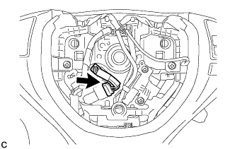
Disconnect the connector.
-
-
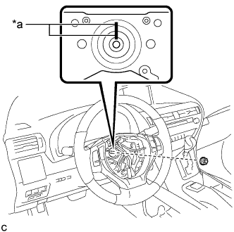
Remove the steering wheel assembly set nut.
Table 2. Text in Illustration *a Matchmark -
Put matchmarks on the steering wheel assembly and steering main shaft.
-
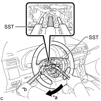
Using SST, remove the steering wheel assembly.
Table 3. Text in Illustration *a Turn *b Hold 09950-50013 09951-05010 09952-05010 09953-05020 09954-05070 Note:Apply a small amount of grease to the threads and tip of SST (09953-05020) before use.
-
- Click here
REMOVE BRAKE PEDAL SUPPORT ASSEMBLY (for LHD)
Tip:Refer to the instructions for Removal of the brake pedal support assembly (Click here).
- Click here
REMOVE BRAKE PEDAL SUPPORT ASSEMBLY (for RHD)
Tip:Refer to the instructions for Removal of the brake pedal support assembly (Click here).
- Click here
REMOVE STEERING COLUMN COVER
Note:Removing the lower steering column cover in the incorrect order will cause the parts to break.
-
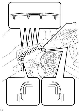
Disengage the 4 clips and 2 guides to separate the instrument panel cluster finish panel from the upper steering column cover.
Table 4. Text in Illustration *1 Instrument Panel Cluster Finish Panel -
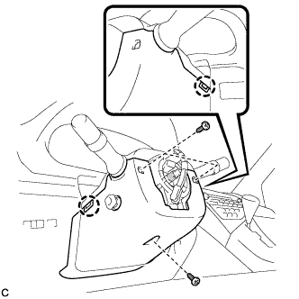
Remove the 3 screws.
-
Disengage the 2 claws to remove the lower steering column cover.
Note:Do not damage the tilt and telescopic switch.
-
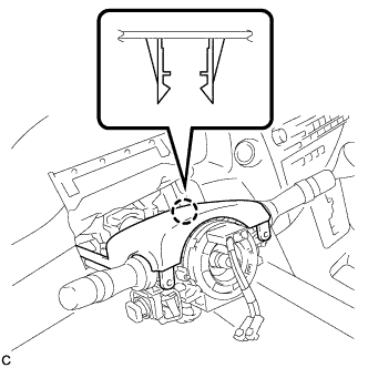
Disengage the claw to remove the upper steering column cover.
-
- Click here
REMOVE TURN SIGNAL SWITCH ASSEMBLY WITH SPIRAL CABLE SUB-ASSEMBLY
-
Disconnect the connectors from the turn signal switch assembly with spiral cable sub-assembly.
-
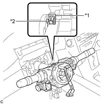
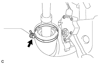
Using pliers, expand the clamp.
Table 5. Text in Illustration *1 Clamp *2 Claw -
While holding the clamp expanded, raise the claw using a screwdriver to disengage it, and then remove the turn signal switch assembly with spiral cable sub-assembly from the steering column assembly.
-
- Click here
SEPARATE STEERING INTERMEDIATE SHAFT ASSEMBLY
-
Loosen the bolt.
-
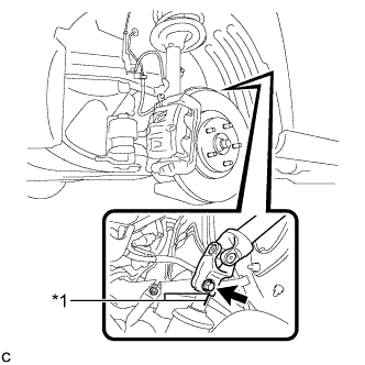
Put matchmarks on the steering intermediate shaft assembly and power steering link assembly.
Table 6. Text in Illustration *1 Matchmark Note:Do not separate the steering intermediate shaft assembly from the power steering link assembly.
-
Remove the bolt.
-
Separate the steering intermediate shaft assembly from the power steering link assembly.
-
- Click here
REMOVE STEERING POST ASSEMBLY
-
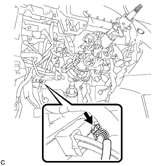
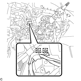
Disconnect the connector from the power steering ECU assembly.
-
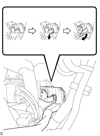
Disconnect the connector from the power steering ECU assembly.
Tip:As shown in the illustration, turn the lock lever to disconnect the connector.
-
Disconnect the connectors and disengage the wire harness clamps from the steering post assembly.
-
Disengage the 2 wire harness clamps.
-
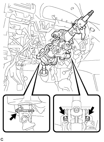
Remove the bolt, 2 nuts and steering post assembly.
-
- Click here
REMOVE STEERING INTERMEDIATE SHAFT ASSEMBLY
-
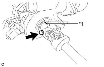
Remove the bolt.
Table 7. Text in Illustration *1 Matchmark -
Put matchmarks on the steering intermediate shaft assembly and steering column assembly.
-
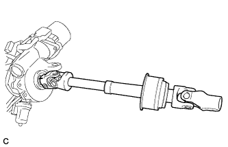
Remove the steering intermediate shaft assembly from the steering column assembly.
-