BRAKE MASTER CYLINDER (for RHD) REMOVAL

-
PRECAUTION (w/ Air Suspension)
Note
Be sure to read Precaution thoroughly before servicing Click here.
-
PRECAUTION (w/ Navigation System for HDD)
Note
After the power switch is turned off, the display and navigation module display (HDD navigation system) records various types of memory and settings. As a result, after turning the power switch off, make sure to wait for the time specified in the following table before disconnecting the cable from the negative (-) auxiliary battery terminal.
Waiting Time before Disconnecting Cable from Negative (-) Auxiliary Battery Terminal Specification Waiting Time w/o Telematics transceiver 60 sec. w/ Telematics transceiver 120 sec. -
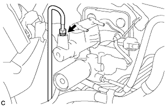
DISCONNECT BRAKE BOOSTER PUMP CONNECTOR
-
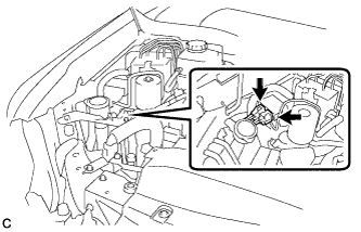
With the power switch off, disconnect the 2 brake booster pump connectors.
-
-
PERFORM ACCUMULATOR ZERO DOWN
-
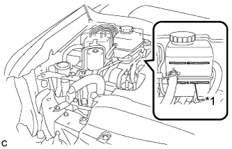
Text in Illustration *1 MIN Line Drain the brake fluid in the reservoir tank near the MIN line.
-
Connect the intelligent tester to the DLC3 with the power switch off.
-
Turn the power switch on (IG).
-
Turn the intelligent tester on and enter the following menus: Chassis / ABS/VSC/TRC / Utility / ECB (Electronically Controlled Brake system) Utility / Zero Down.
Tech Tips
Using the intelligent tester to perform accumulator zero down causes the pressurized fluid in the accumulator to be returned to the brake fluid reservoir.
-
When the buzzer sounds, turn the power switch off.
-
Turn the intelligent tester off.
-
-
DRAIN BRAKE FLUID
Note
-
If brake fluid leaks onto any painted surface, immediately clean it off.
-
If air has leaked into the No. 2 brake actuator hose (the hose between the brake booster pump and brake fluid reservoir), use the same bleeding method as for the brake actuator assembly.
-
-
REMOVE REAR DECK FLOOR BOX
-
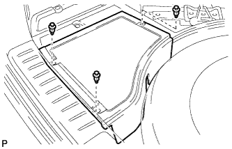
Remove the 3 clips and the rear deck floor box.
-
-
DISCONNECT CABLE FROM NEGATIVE AUXILIARY BATTERY TERMINAL
Note
When disconnecting the cable, some systems need to be initialized after the cable is reconnected Click here.
-
REMOVE WINDSHIELD WIPER MOTOR AND LINK ASSEMBLY
Tech Tips
Refer to the instructions for Removal of the windshield wiper motor and link assembly Click here.
-
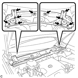
REMOVE FRONT SHOCK ABSORBER CAP LH (w/ Air Suspension)
-
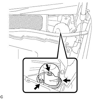
Remove the 3 nuts and front shock absorber cap.
-
-
REMOVE FRONT SHOCK ABSORBER CAP RH (w/ Air Suspension)
Tech Tips
Use the same procedure for the LH side and RH side.
-
REMOVE OUTER COWL TOP PANEL SUB-ASSEMBLY
-
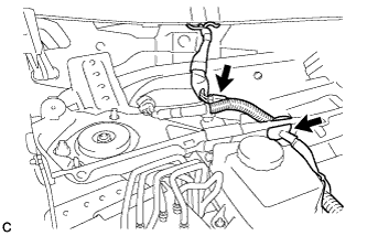
Disconnect the connector (w/ Windshield Deicer).
-
Disengage the grommet and clamp, and separate the wire harness.
-
Remove the 6 nuts, 4 bolts and outer cowl top panel sub-assembly.
-
-
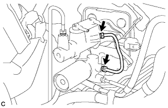
DISCONNECT NO. 1 RESERVOIR HOSE
-
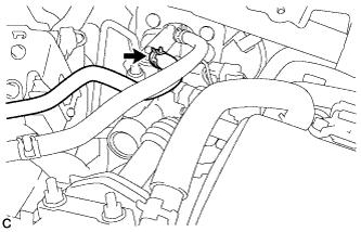
Slide the clip and disconnect the No. 1 reservoir hose from the brake master cylinder sub-assembly.
-
-
DISCONNECT NO. 2 RESERVOIR HOSE
-
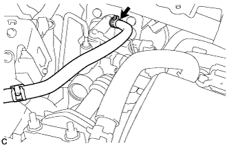
Slide the clip and disconnect the No. 2 reservoir hose from the brake master cylinder sub-assembly.
-
-
REMOVE NO. 1 INSTRUMENT PANEL UNDER COVER SUB-ASSEMBLY
-
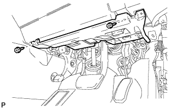
Remove the 2 screws <D>.
-
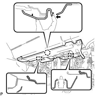
Disengage the claw and 2 guides as shown in the illustration.
-
Disconnect each connector.
-
Disengage each clamp and remove the No. 1 instrument panel under cover sub-assembly.
-
-
REMOVE BRAKE PEDAL RETURN SPRING
-
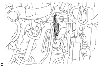
Remove the brake pedal return spring from the push rod pin and brake pedal support sub-assembly.
-
-
SEPARATE MASTER CYLINDER PUSH ROD CLEVIS
-
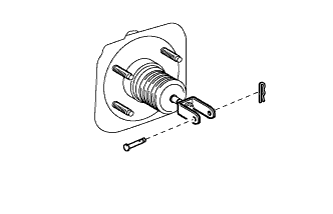
Remove the clip and push rod pin, and separate the master cylinder push rod clevis from the brake pedal sub-assembly.
-
-
REMOVE BRAKE STROKE SIMULATOR TUBE
-
Using a union nut wrench, disconnect the 2 union nuts to remove the brake stroke simulator tube.
-
-
REMOVE BRAKE MASTER CYLINDER SUB-ASSEMBLY
-
Using a union nut wrench, disconnect the No. 6 front brake tube from the brake master cylinder sub-assembly.
-
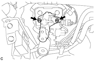
Remove the 2 nuts and brake master cylinder sub-assembly.
-
Remove the brake master cylinder gasket from the brake master cylinder sub-assembly.
-
-
REMOVE BRAKE STROKE SIMULATOR CYLINDER WITH BRACKET
-
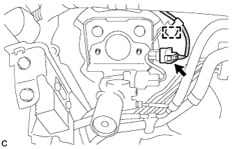
Disconnect the connector and disengage the clamp.
-
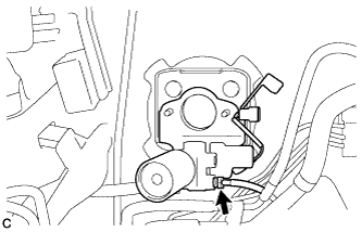
Using a union nut wrench, disconnect the No. 7 front brake tube from the brake stroke simulator cylinder sub-assembly.
-
Remove the brake stroke simulator cylinder with bracket from the brake master cylinder bracket.
-
Remove the brake master cylinder gasket from the brake master cylinder bracket.
-
-
REMOVE BRAKE MASTER CYLINDER BRACKET
-
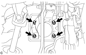
Remove the 4 nuts and brake master cylinder bracket.
-
-
REMOVE BRAKE BOOSTER GASKET
-
Remove the brake booster gasket from the brake master cylinder bracket.
-