PARKING ASSIST MONITOR SYSTEM (w/ Side Monitor System) CALIBRATION

-
ADJUST PARKING ASSIST MONITOR SYSTEM
-
This parking assist monitor system can be set from the diagnostic screen of the multi-display assembly.
-
If the following operations are performed, it is necessary to perform adjustments and checks on the diagnostic screen.
Part Name Operation Adjustment Item Proceed to Spiral cable with sensor sub-assembly
-
Removal and installation of the spiral cable with sensor sub-assembly
-
Removal and installation of the connector of the spiral cable with sensor sub-assembly
-
Replacement
Steering angle neutral point Steering angle setting Procedure 2 Parking assist ECU Replacement Parking assist ECU initialization Procedure 1 Suspension, tires, etc. The vehicle height changes because of suspension or tire replacement Rear television camera optical axis (Back camera position setting) Procedure 3 Side television camera optical axis (Side camera position setting) Rear television camera assembly
-
Replacement
-
Installation angle of the rear television camera changes because of the removal and installation of the rear television camera, etc.
Rear television camera optical axis (Back camera position setting) Procedure 3 Multi-media module receiver assembly Replacement Parking assist ECU initialization Procedure 1 Tech Tips
The adjustment values stored while performing parking assist monitor system calibration are stored in the parking assist ECU.
-
-
-
PARKING ASSIST ECU INITIALIZATION (Procedure 1)
Tech Tips
Be sure to check for DTCs before performing this procedure Click here.
-
Preparation for adjustment
-
Park the vehicle with the steering wheel centered.
-
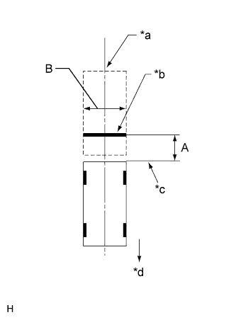
Text in Illustration *a Vehicle Center *b Target Bar for Back Camera Adjustment *c Vehicle End *d Front Side Set a target bar for optical axis adjustment of the rear television camera assembly.
Tech Tips
Only when adjusting the optical axis of the camera, create a target bar for adjustment.
Tech Tips
-
Set a piece of tape on the ground as the target bar for adjustment. Its width and length are 20 to 30 mm (0.787 to 1.18 in.) and 1995 to 2005 mm (6.55 to 6.58 ft.), respectively. Check the color on the multi-display assembly and choose a tape color which can be easily seen.
-
Before parking the vehicle, be sure to move the vehicle forward and in reverse to check that the tires are facing straight ahead with the steering wheel centered.
-
Check that the back door is fully closed.
-
-
Set a target bar for optical axis adjustment of the side television camera assembly.
Tech Tips
Only when adjusting the optical axis of the camera, create a target bar for adjustment.
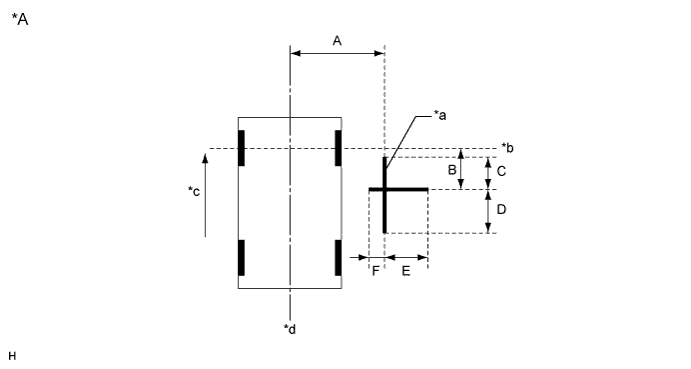
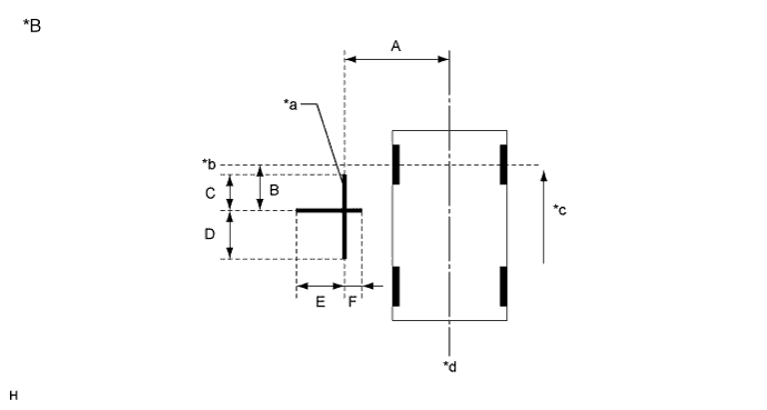
Text in Illustration *A for LHD *B for RHD *a Target Bar for Side Camera Adjustment *b Front Wheel Axis *c Front Side *d Vehicle Center Tech Tips
Target bars for side camera adjustment should be made with 2 pieces of 25 mm (0.98 in.) wide tape; one piece should be 1000 mm (3.28 ft.) (C+D) and the other should be 700 mm (2.30 ft.) (E+F) long. Check the tape color on the multi-media module receiver assembly and choose a tape color which can be easily seen.
-
-
Start diagnostic mode Click here.
Note
Alignment must be performed with the power switch on (READY). For this reason, it is necessary to apply the parking brake, depress the brake pedal, and move the shift lever into the P position, and to exercise all other necessary caution to ensure that the vehicle does not begin moving unexpectedly.
Tech Tips
The displayed items may differ depending on vehicle specifications.
-
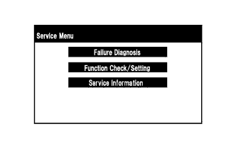
Select "Function Check/Setting" on the [Service Menu] screen.
-
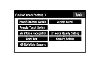
Select "Camera Setting" on the [Function Check/Setting I] screen.
-
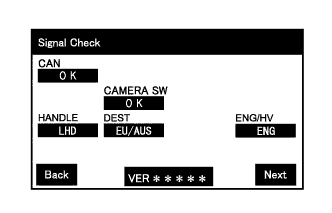
Select "Next" on the [Signal Check] screen.
Note
-
When "CHK" (red) is displayed for any items on the [Signal Check] screen, selecting "Next" will not change the screen to the [Side Camera Position Setting] screen.
-
When "CHK" (red) or incorrect vehicle specification is displayed for any items on the [Signal Check] screen, perform inspections using the [Signal Check] screen Click here.
Tech Tips
When the outer mirrors are retracted, selecting "Next" will not change the screen to the [Side Camera Position Setting] screen.
-
-
-
Side Camera Position Setting:
Tech Tips
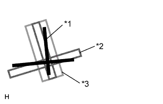
Colors used on the [Side Camera Position Setting] screen
Text in Illustration *1 Target Adjustment Bar for Side Camera Position Setting *2 Red Frame *3 Yellow Frame
-
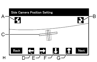
Perform the roll angle adjustment.
-
Select switches A and B to rotate C so that it is parallel to the target adjustment bar.
-
-
Perform the vertical and horizontal position adjustment.
-
Select the directional switches D, E, F and G to move C so that the target adjustment bar is centered in C.
-
-
Select "Next" to display [Side Verify Mode].
-
-
Side Verify Mode:
-
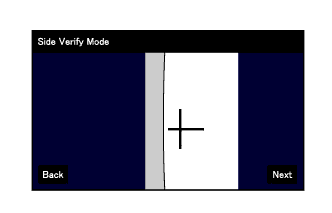
Check that the red cross and the target adjustment bar are aligned.
Tech Tips
If they are not aligned, select "Back" and perform [Side Camera Position Setting] again.
-
Select "Next" to display [Steering Angle Setting].
-
-
Steering Angle Setting:
-
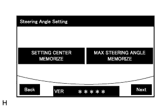
Perform the "STEERING CENTER MEMORIZE" operation.
-
Check that the steering wheel is centered (approximately +/- 5 degrees or less) and then select "STEERING CENTER MEMORIZE".
Tech Tips
When performing removal and installation, or replacement of the television camera, steering angle adjustment is not required.
-
-
Perform the "MAX STEERING ANGLE MEMORIZE" operation.
-
After adjusting the steering angle neutral point, turn the steering wheel to the left and right lock positions and select "MAX STEERING ANGLE MEMORIZE". The maximum steering angle is then stored and the screen changes to the [Back Camera Position Setting] screen.
Tech Tips
-
The "Next" button does not respond until the system stores the steering angle neutral point and maximum steering angle.
-
It is also possible to start by initially turning the steering to the right side.
-
When "MAX STEERING ANGLE MEMORIZE" is selected, a beep will sound to confirm that the steering adjustment values have been stored.
-
The adjustment value will not be stored unless "MAX STEERING ANGLE MEMORIZE" is selected after turning the steering wheel side to side.
-
When "Back" is selected, the screen changes to [Side Verify Mode] without storing the set values.
-
Even if no DTCs are detected, selecting "MAX STEERING ANGLE MEMORIZE" may not cause the adjustment value to be stored if the spiral cable with sensor sub-assembly is malfunctioning.
-
If selecting "MAX STEERING ANGLE MEMORIZE" does not cause the adjustment value to be stored after adjusting the steering angle, replace the spiral cable with sensor sub-assembly Click here.
-
-
-
-
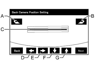
Back Camera Position Setting:
Tech Tips
-
When the back door is open, the "Back door is open. Do not use the rear view monitor when the back door is not completely closed." message will be displayed and camera position setting will not be possible.
-
If the "Back door is open. Do not use the rear view monitor when the back door is not completely closed." message is displayed even when the back door is closed, perform inspections according to Problem Symptoms Table (When adjusting the camera optical axis, "Back door is open. Do not use the rear view monitor when the back door is not completely closed." is displayed even after the back door has been closed.) Click here.
-
Perform the roll angle adjustment.
-
Select switches A and B to rotate C so that it is parallel to the target adjustment bar.
-
-
Perform the vertical and horizontal position adjustment.
-
Select the directional switches D, E, F and G to move C so that the target adjustment bar is centered in C.
-
-
Select the "Next" to display [Back Verify Mode].
-
-
Back Verify Mode:
-
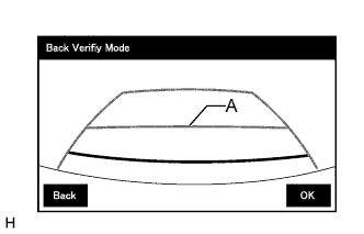
Check that A and the target adjustment bar are overlapping.
-
If the steering angle neutral point is not aligned, perform the "STEERING CENTER MEMORIZE" and "MAX STEERING ANGLE MEMORIZE" operations.
-
If A and the target adjustment bar are not aligned even if the tires are aligned straight ahead, perform the camera position setting operation.
-
-
Selecting "OK" will return the screen to the [Service Menu] screen, and complete the adjustment.
Tech Tips
-
The update is not completed until "OK" is selected.
-
When "OK" is selected, a beep will sound to confirm that the rear camera aiming adjustment values have been stored.
-
-
-
Finish diagnostic mode Click here.
-
-
STEERING ANGLE SETTING (Procedure 2)
-
Preparation for adjustment
-
Park the vehicle with the steering wheel centered.
-
-
Start diagnostic mode Click here.
Note
Alignment must be performed with the power switch on (READY). For this reason, it is necessary to apply the parking brake, depress the brake pedal, and move the shift lever into the P position, and to exercise all other necessary caution to ensure that the vehicle does not begin moving unexpectedly.
Tech Tips
The displayed items may differ depending on vehicle specifications.
-
Select "Function Check/Setting" on the [Service Menu] screen.
-
Select "Camera Setting" on the [Function Check/Setting I] screen.
-
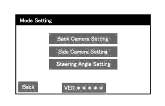
Select "Steering Angle Setting" on the [Mode Setting] screen.
Tech Tips
To select a grayed out item, select and hold the item for 2 seconds or more.
-
Select "Next" on the [Signal Check] screen.
Note
-
When "CHK" (red) is displayed for any items on the [Signal Check] screen, selecting "Next" will not change the screen to the [Steering Angle Setting] screen.
-
When "CHK" (red) or incorrect vehicle specification is displayed for any items on the [Signal Check] screen, perform inspections using the [Signal Check] screen Click here.
-
-
-
Steering Angle Setting:
-
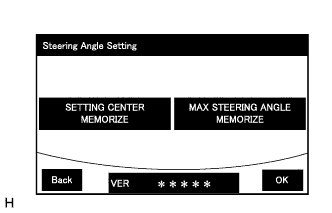
Perform the "STEERING CENTER MEMORIZE" operation.
-
Check that the steering wheel is centered (approximately +/- 5 degrees or less) and then select "STEERING CENTER MEMORIZE".
Tech Tips
When performing removal and installation, or replacement of the television camera, steering angle adjustment is not required.
-
-
Perform the "MAX STEERING ANGLE MEMORIZE" operation.
-
After adjusting the steering angle neutral point, turn the steering wheel to the left and right lock positions and select "MAX STEERING ANGLE MEMORIZE". The maximum steering angle is then stored and the screen changes to the [Mode Setting] screen.
Tech Tips
-
The "Next" button does not respond until the system stores the steering angle neutral point and maximum steering angle.
-
It is also possible to start by initially turning the steering to the right side.
-
When "MAX STEERING ANGLE MEMORIZE" is selected, a beep will sound to confirm that the steering adjustment values have been stored.
-
The adjustment value will not be stored unless "MAX STEERING ANGLE MEMORIZE" is selected after turning the steering wheel side to side.
-
When "Back" is selected, the screen changes to [Signal Check] without storing the set values.
-
Even if no DTCs are detected, selecting "MAX STEERING ANGLE MEMORIZE" may not cause the adjustment value to be stored if the spiral cable with sensor sub-assembly is malfunctioning.
-
If selecting "MAX STEERING ANGLE MEMORIZE" does not cause the adjustment value to be stored after adjusting the steering angle, replace the spiral cable with sensor sub-assembly Click here.
-
-
Select "OK" to display [Mode Setting].
-
-
Finish diagnostic mode Click here.
-
Confirm steering angle adjustment.
Tech Tips
If the steering angle has been adjusted, confirm the steering angle adjustment on the parking assist monitor screen after finishing diagnostic mode.
-
Check on the parking assist screen that the predicted path line moves until the steering wheel is fully turned to either the left or right.
Tech Tips
If the predicted path line stops moving before the steering wheel is fully turned to either the left or right, the steering angle adjustment values have not been stored correctly. In this case, perform "STEERING CENTER MEMORIZE" and "MAX STEERING ANGLE MEMORIZE" again.
-
-
-
BACK CAMERA POSITION SETTING (Procedure 3)
Tech Tips
Be sure to check for DTCs before performing this procedure Click here.
-
Preparation for adjustment
-
Park the vehicle with the steering wheel centered.
-
Text in Illustration *a Vehicle Center *b Target Bar for Back Camera Adjustment *c Vehicle End *d Front Side Set a target bar for optical axis adjustment of the rear television camera assembly.
Tech Tips
Only when adjusting the optical axis of the camera, create a target bar for adjustment.
Tech Tips
-
Set a piece of tape on the ground as the target bar for adjustment. Its width and length should be 20 to 30 mm (0.787 to 1.18 in.) and 1995 to 2005 mm (6.55 to 6.58 ft.), respectively. Check the color on the multi-display and choose a tape color which can be easily seen.
-
Before parking the vehicle, be sure to move the vehicle forward and in reverse to check that the tires are facing straight ahead with the steering wheel centered.
-
Check that the back door is fully closed.
-
-
-
Start diagnostic mode Click here.
Note
Alignment must be performed with the power switch on (READY). For this reason, it is necessary to apply the parking brake, depress the brake pedal, and move the shift lever into the P position, and to exercise all other necessary caution to ensure that the vehicle does not begin moving unexpectedly.
Tech Tips
The displayed items may differ depending on vehicle specifications.
-
Select "Function Check/Setting" on the [Service Menu] screen.
-
Select "Camera Setting" on the [Function Check/Setting I] screen.
-
Select "Back Camera Setting" on the [Mode Setting] screen.
Tech Tips
To select a grayed out item, select and hold the item for 2 seconds or more.
-
Select "Next" on the [Signal Check] screen.
Note
-
When "CHK" (red) is displayed for any items on the [Signal Check] screen, selecting "Next" will not change the screen to the [Back Camera Position Setting] screen.
-
When "CHK" (red) or incorrect vehicle specification is displayed for any items on the [Signal Check] screen, perform inspections using the [Signal Check] screen Click here.
-
-
-
Back Camera Position Setting:
Tech Tips
-
When the back door is open, the "Back door is open. Do not use the rear view monitor when the back door is not completely closed." message will be displayed and camera position setting will not be possible.
-
If the "Back door is open. Do not use the rear view monitor when the back door is not completely closed." message is displayed even when the back door is closed, perform inspections according to Problem Symptoms Table (When adjusting the camera optical axis, "Back door is open. Do not use the rear view monitor when the back door is not completely closed." is displayed even after the back door has been closed) Click here.
-
Perform the roll angle adjustment.
-
Select switches A and B to rotate C so that it is parallel to the target adjustment bar.
-
-
Perform the vertical and horizontal position adjustment.
-
Select the directional switches D, E, F and G to move C so that the target adjustment bar is centered in C.
-
-
Select the "Next" button on the [Back Camera Position Setting] screen.
-
-
Back Verify Mode:
-
Check that A and the target adjustment bar are overlapping.
-
If the steering angle neutral point is not aligned, perform the "STEERING CENTER MEMORIZE" and "MAX STEERING ANGLE MEMORIZE" operations.
-
If A and the target adjustment bar are not aligned even if the tires are aligned straight ahead, perform the camera position setting operation.
-
-
Selecting "OK" will return the screen to the [Service Menu], and complete the adjustment.
Tech Tips
-
The update is not completed until "OK" is selected.
-
When "OK" is selected, a beep will sound to confirm that the rear camera aiming adjustment values have been stored.
-
-
-
Finish diagnostic mode Click here.
-