LIGHTING SYSTEM TERMINALS OF ECU

-
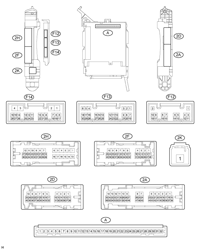
CHECK INSTRUMENT PANEL JUNCTION BLOCK ASSEMBLY AND MAIN BODY ECU (MULTIPLEX NETWORK BODY ECU)
-
Disconnect the 2A, 2D, 2F, 2K and F14 instrument panel junction block assembly and main body ECU (multiplex network body ECU) connectors.
-
Measure the voltage according to the value(s) in the table below.
Terminal No. (Symbol) Wiring Color Terminal Description Condition Specified Condition 2A-17 - Body ground GR - Body ground ACC power supply Engine switch on (ACC) 11 to 14 V Engine switch off Below 1 V 2A-20 - Body ground G - Body ground IG power supply Engine switch on (IG) 11 to 14 V Engine switch off Below 1 V 2F-40 (BECU)- Body ground G - Body ground Battery power supply Always 11 to 14 V 2K-1 - Body ground W - Body ground Battery power supply Always 11 to 14 V If the result is not as specified, there may be a malfunction in the wire harness.
-
Measure the resistance according to the value(s) in the table below.
Terminal No. (Symbol) Wiring Color Terminal Description Condition Specified Condition 2D-6 (GND1) - Body ground BR - Body ground Ground Always Below 1 Ω F14-3 (GND2) - Body ground W-B - Body ground Ground Always Below 1 Ω If the result is not as specified, there may be a malfunction in the wire harness.
-
Reconnect the 2A, 2D, 2F, 2K and F14 instrument panel junction block assembly and main body ECU (multiplex network body ECU) connectors.
-
Measure the voltage or check for pulses according to the value(s) in the table below.
Terminal No. (Symbol) Wiring Color Terminal Description Condition Specified Condition 2A-41 (RFGO)*1 - Body ground R - Body ground Rear fog lights drive output Light control switch in tail position and rear fog light switch on Below 1 V Light control switch in tail position and rear fog light switch off 11 to 14 V 2D-26 (FRCY) - Body ground L - Body ground Front door courtesy light switch RH input Front door RH open Below 1 V Front door RH closed 11 to 14 V 2F-20 (DIM) - Body ground G - Body ground High beam headlights drive output Dimmer switch in high or high flash position Below 1 V Dimmer switch in low position 11 to 14 V 2F-37 (HRLY) - Body ground B - Body ground Headlight relay drive output Light control switch in head position Below 1 V Light control switch not in head position 11 to 14 V 2H-26 (FLCY) - Body ground B - Body ground Front door courtesy light switch LH input Front door LH open Below 1 V Front door LH closed 11 to 14 V 2H-27 (LSWL) - Body ground Y - Body ground Rear door unlock detection switch LH input Rear door LH locked Pulse generation Rear door LH unlocked Below 1 V F13-1 (RFOG)*1 - Body ground SB - Body ground Rear fog light switch input Rear fog light switch on Below 1 V Rear fog light switch off 11 to 14 V F12-3 (LCTY) - Body ground L - Body ground Rear door courtesy light switch LH input Rear door LH open Below 1 V Rear door LH closed 11 to 14 V F13-6 (RCTY) - Body ground GR - Body ground Rear door courtesy light switch RH input Rear door RH open Below 1 V Rear door RH closed Pulse generation F13-7 (LSFL) - Body ground P - Body ground Front door unlock detection switch LH input Front door LH locked Pulse generation Front door LH unlocked Below 1 V F13-8 (HF) - Body ground Y - Body ground Dimmer switch high flash position signal input Dimmer switch in high flash position Below 1 V Dimmer switch not in high flash position Pulse generation F13-15 (DRL) - Body ground GR - Body ground Daytime running light system drive output Daytime running light system operates Below 1 V Daytime running light system does not operate 11 to 14 V F13-18 (LSFR) - Body ground SB - Body ground Front door unlock detection RH switch input Front door RH locked Pulse generation Front door RH unlocked Below 1 V F13-19 (BCTY)*2 - Body ground R - Body ground Back door courtesy light switch input Back door open Below 1 V Back door closed 11 to 14 V F13-20 (CLTB) - Body ground L - Body ground Automatic light control sensor power supply output Engine switch off Below 1 V Engine switch on (IG) and light control switch in AUTO position 11 to 14 V F13-21 (CLTS) - Body ground B - Body ground Automatic light control sensor signal input Engine switch off Below 1 V Automatic light control system operates Pulse generation
(See waveform 1)
F13-27 (FFOG) - Body ground P - Body ground Front fog light switch input Front fog light switch on Below 1 V Front fog light switch off Pulse generation F13-28 (A) - Body ground BR - Body ground Light control switch AUTO position signal input Light control switch in AUTO position Below 1 V Light control switch not in AUTO position Pulse generation F13-29 (HEAD) - Body ground SB - Body ground Light control switch head position input Light control switch in head position Below 1 V Light control switch not in head position and engine switch off Pulse generation Light control switch not in head position and engine switch on (IG) 11 to 14 V F13-30 (TAIL) - Body ground V - Body ground Light control switch tail position signal input Light control switch in tail or head position Below 1 V Light control switch in neither tail nor head position, and engine switch off Pulse generation Light control switch in neither tail nor head position, and engine switch on (IG) 11 to 14 V F14-2 (LSWR) - Body ground B - Body ground Rear door unlock detection switch RH input Rear door RH locked Pulse generation Rear door RH unlocked Below 1 V Tech Tips
-
*1: w/ Rear Fog Light
-
*2: w/o Power Back Door
If the result is not as specified, the main body ECU (multiplex network body ECU) or instrument panel junction block assembly may have a malfunction.
-
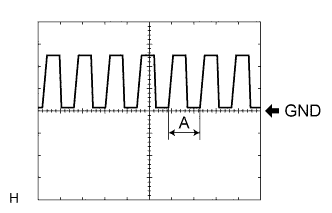
Waveform 1
Item Content Tool setting 5 V/DIV., 5 ms./DIV. Tech Tips
If the ambient light becomes brighter, width A becomes narrower.
-
-
-
CHECK AFS ECU (HEADLIGHT SWIVEL ECU ASSEMBLY)
-
Disconnect the A53 AFS ECU (headlight swivel ECU assembly) connector.

-
Measure the resistance according to the value(s) in the table below.
Terminal No. (Symbol) Wiring Color Terminal Description Condition Specified Condition A53-22 (E1) - Body ground W-B - Body ground AFS ECU (headlight swivel ECU assembly) ground Always Below 1 Ω If the result is not as specified, there may be a malfunction in the wire harness.
-
Measure the voltage according to the value(s) in the table below.
Terminal No. (Symbol) Wiring Color Terminal Description Condition Specified Condition A53-14 (IGS)*1 - Body ground LG - Body ground Swivel motor power supply Engine switch off Below 1 V Engine switch on (IG) 11 to 14 V A53-15 (IG) - Body ground V - Body ground AFS ECU (headlight swivel ECU assembly) power supply Engine switch off Below 1 V Engine switch on (IG) 11 to 14 V If the result is not as specified, there may be a malfunction in the wire harness.
-
Reconnect the A53 AFS ECU (headlight swivel ECU assembly) connector.
-
Measure the resistance according to the value(s) in the table below.
Terminal No. (Symbol) Wiring Color Terminal Description Condition Specified Condition A53-21 (SGR) - A53-22 (E1) B*2 - W-B
P*3 - W-B
Height control sensor ground Always Below 1 Ω A53-23 (SMGL)*1 - A53-22 (E1) BR - W-B Swivel motor LH ground Always Below 1 Ω A53-24 (SMGR)*1 - A53-22 (E1) B - W-B Swivel motor RH ground Always Below 1 Ω If the result is not as specified, the AFS ECU (headlight swivel ECU assembly) may have a malfunction.
-
Measure the voltage or check for pulses according to the value(s) in the table below.
Terminal No. (Symbol) Wiring Color Terminal Description Condition Specified Condition A53-1 (SMBL)*1 - A53-22 (E1) GR - W-B Swivel motor LH power supply Engine switch off Below 1 V Engine switch on (IG) 11 to 16 V A53-2 (SMBR)*1 - A53-22 (E1) R - W-B Swivel motor RH power supply Engine switch off Below 1 V Engine switch on (IG) 11 to 16 V A53-7 (INIT) - A53-22 (E1) W - W-B Initialization signal Engine switch on (IG), terminals LVL and GND of DLC3 connected Below 1 V Engine switch on (IG), terminals LVL and GND of DLC3 not connected Approx. 5 V A53-10 (SMR)*1 - A53-22 (E1) L - W-B Swivel motor RH for swivel function LIN communication Engine switch off Below 1 V Engine switch on (IG) Pulse generation A53-11 (RH+) - A53-22 (E1) V - W-B Swivel motor RH for leveling function LIN communication Engine switch off Below 1 V Engine switch on (IG) Pulse generation A53-12 (CANH) - A53-22 (E1) B - W-B CAN communication Engine switch off Below 1 V Engine switch on (IG) Pulse generation A53-13 (CANL) - A53-22 (E1) W - W-B CAN communication Engine switch off Below 1 V Engine switch on (IG) Pulse generation A53-17 (SHFL)*3 - A53-21 (SGR) Y - B*2
Y - P*3
Front height control sensor signal Engine switch off Below 1 V Engine switch on (IG) 1 to 4 V A53-18 (SBR) - A53-21 (SGR) BR*2 - B*2
G*3 - P*3
Height control sensor power supply Engine switch off Below 1 V Engine switch on (IG) Approx. 5 V A53-19 (SHRL) - A53-21 (SGR) L*2 - B*2
L*3 - P*3
Rear height control sensor signal Engine switch off Below 1 V Engine switch on (IG) 1 to 4 V A53-29 (SML)*1 - A53-22 (E1) P - W-B Swivel motor LH for swivel function LIN communication Engine switch off Below 1 V Engine switch on (IG) Pulse generation A53-30 (LH+) - A53-22 (E1) GR - W-B Swivel motor LH for leveling function LIN communication Engine switch off Below 1 V Engine switch on (IG) Pulse generation Tech Tips
-
*1: w/ AFS
-
*2: w/o Air Suspension
-
*3: w/ Air Suspension
If the result is not as specified, the AFS ECU (headlight swivel ECU assembly) may have a malfunction.
-
-