-
Use the same procedure for the RH side and LH side.
-
The procedure listed below is for the LH side.
- Click here
INSTALL SIDE AIRBAG SENSOR
-
Check that the engine switch is off.
-
Check that the cable is disconnected from the negative (-) battery terminal.
CAUTION:Wait at least 90 seconds after disconnecting the cable from the negative (-) battery terminal to disable the SRS system.
-
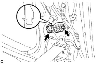
Insert the pin (stopper) into the body hole to install the side airbag sensor to the vehicle with the bolt.
9.0 N*m 92 kgf*cm 80 in.*lbf Note:
-
If the side airbag sensor has been dropped, or there are any cracks, dents or other defects in the case or connector, replace it with a new one.
-
When installing the side airbag sensor, be careful that the SRS wiring does not interfere with or is not pinched between other parts.
-
Make sure that the pin (stopper) is securely inserted into the body hole.
-
Tighten the bolt while holding the side airbag sensor because the side airbag sensor pin (stopper) is easily damaged.
-
-
Connect the connector to the side airbag sensor.
Note:When connecting the airbag connector, take care not to damage the airbag wire harness.
-
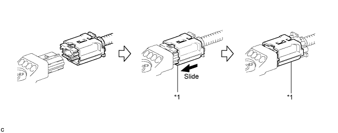
Connect the connector as shown in the illustration (when locking, make sure that the outer connector locking sleeve returns to its original position and a click sound can be heard).
Table 1. Text in Illustration *1 Outer Connector Locking Sleeve - - Tip:When connected, the outer connector locking sleeve will slide. Be sure not to hold the outer connector locking sleeve while connecting, as it may result in an insecure fit.
-
-
Check that there is no looseness in the installation parts of the side airbag sensor.
-
- Click here
INSTALL LOWER CENTER PILLAR GARNISH
-
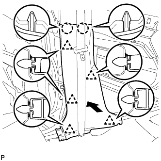
Engage the 2 claws and the 5 clips to install the lower center pillar garnish LH.
-
- Click here
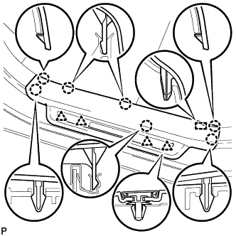
INSTALL REAR DOOR SCUFF PLATE
-
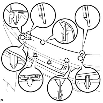
Engage the 3 clips, guide and 6 claws, and install the rear door scuff plate LH.
-
- Click here
INSTALL FRONT DOOR SCUFF PLATE
-
w/ Illumination:
-
Connect the connector.
-
-
Engage the 4 clips, guide and 7 claws, and install the front door scuff plate LH.
-
- Click here
CONNECT CABLE TO NEGATIVE BATTERY TERMINAL
Note:When disconnecting the cable, some systems need to be initialized after the cable is reconnected (Click here).
- Click here
PERFORM DIAGNOSTIC SYSTEM CHECK
-
Perform a diagnostic system check (Click here).
-
- Click here
INSPECT SRS WARNING LIGHT
-
Inspect the SRS warning light (Click here).
-