DESCRIPTION
The seat belt buckle switch LH circuit consists of the center airbag sensor assembly and front seat inner belt assembly LH.
DTC B1656/38 is recorded when a malfunction is detected in the seat belt buckle switch LH circuit.
| DTC No. | DTC Detection Condition | Trouble Area |
|---|---|---|
| B1656/38 |
|
|
INSPECTION PROCEDURE
PROCEDURE
- Click here
CHECK CONNECTORS
-
Turn the engine switch off.
-
Disconnect the cable from the negative (-) battery terminal.
Note:Wait at least 90 seconds after disconnecting the cable from the negative (-) battery terminal to disable the SRS system.
-
Check that the connectors are properly connected to the center airbag sensor assembly and front seat inner belt assembly LH.
OK The connectors are properly connected. Tip:If the connectors are not connected securely, reconnect the connectors and proceed to the next inspection.
-
Disconnect the connectors from the center airbag sensor assembly and front seat inner belt assembly LH.
-
Check that the terminals of connectors are not damaged.
OK The terminals are not deformed or damaged.
- OKClick here
- NGClick here
-
- Click here
CHECK NO. 2 FLOOR WIRE (OPEN)
-
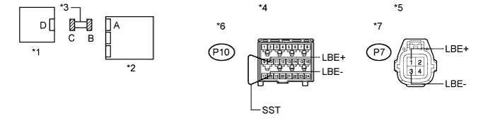
Using SST, connect terminals 10 (LBE+) and 18 (LBE-) of connector B.
Note:Do not forcibly insert SST into the terminals of the connector when connecting the wire.
09843-18040 -
Measure the resistance according to the value(s) in the table below.
Standard Resistance Tester Connection Condition Specified Condition P7-1 (LBE+) - P7-3 (LBE-) Always Below 1 Ω Table 1. Text in Illustration *1 Front Seat Inner Belt Assembly LH (Seat Belt Buckle Switch LH) *2 Center Airbag Sensor Assembly *3 No. 2 Floor Wire *4 Front view of wire harness connector
(to Center Airbag Sensor Assembly)
*5 Front view of wire harness connector
(to Front Seat Inner Belt Assembly LH)
*6 Connector B *7 Connector C - -
- OKClick here
- NGClick here
-
- Click here
CHECK NO. 2 FLOOR WIRE (SHORT)
-
Disconnect SST from connector B.
-
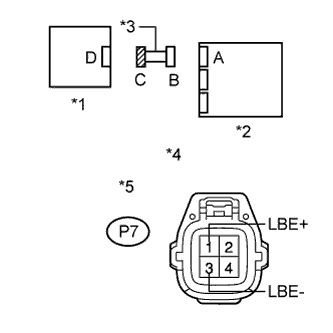
Measure the resistance according to the value(s) in the table below.
Standard Resistance Tester Connection Condition Specified Condition P7-1 (LBE+) - P7-3 (LBE-) Always 1 MΩ or higher Table 2. Text in Illustration *1 Front Seat Inner Belt Assembly LH (Seat Belt Buckle Switch LH) *2 Center Airbag Sensor Assembly *3 No. 2 Floor Wire *4 Front view of wire harness connector
(to Front Seat Inner Belt Assembly LH)
*5 Connector C
- OKClick here
- NGClick here
-
- Click here
CHECK NO. 2 FLOOR WIRE (SHORT TO B+)
-
Connect the cable to the negative (-) battery terminal.
-
Turn the engine switch on (IG).
-
Measure the voltage according to the value(s) in the table below.
Standard Voltage Tester Connection Switch Condition Specified Condition P7-1 (LBE+) - Body ground Engine switch on (IG) Below 1 V P7-3 (LBE-) - Body ground Engine switch on (IG) Below 1 V Table 3. Text in Illustration *1 Front Seat Inner Belt Assembly LH (Seat Belt Buckle Switch LH) *2 Center Airbag Sensor Assembly *3 No. 2 Floor Wire *4 Front view of wire harness connector
(to Front Seat Inner Belt Assembly LH)
*5 Connector C
- OKClick here
- NGClick here
-
- Click here
CHECK NO. 2 FLOOR WIRE (SHORT TO GROUND)
-
Turn the engine switch off.
-
Disconnect the cable from the negative (-) battery terminal.
Note:Wait at least 90 seconds after disconnecting the cable from the negative (-) battery terminal to disable the SRS system.
-
Measure the resistance according to the value(s) in the table below.
Standard Resistance Tester Connection Condition Specified Condition P7-1 (LBE+) - Body ground Always 1 MΩ or higher P7-3 (LBE-) - Body ground Always 1 MΩ or higher Table 4. Text in Illustration *1 Front Seat Inner Belt Assembly LH (Seat Belt Buckle Switch LH) *2 Center Airbag Sensor Assembly *3 No. 2 Floor Wire *4 Front view of wire harness connector
(to Front Seat Inner Belt Assembly LH)
*5 Connector C
- OKClick here
- NGClick here
-
- Click here
CHECK FRONT SEAT INNER BELT ASSEMBLY LH
-
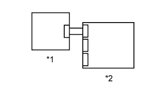
Connect the connectors to the center airbag sensor assembly and front seat inner belt assembly LH.
-
Connect the cable to the negative (-) battery terminal.
-
Turn the engine switch on (IG), and wait for at least 60 seconds.
-
Clear the DTCs stored in the memory (Click here).
-
Turn the engine switch off.
-
Turn the engine switch on (IG), and wait for at least 60 seconds.
-
Check for DTCs (Click here).
OK DTC B1656/38 is not output. Table 5. Text in Illustration *1 Front Seat Inner Belt Assembly LH (Seat Belt Buckle Switch LH) *2 Center Airbag Sensor Assembly Tip:Codes other than DTC B1656/38 may be output at this time, but they are not related to this check.
- OKClick here
- NGClick here
-
- Click here
REPLACE FRONT SEAT INNER BELT ASSEMBLY LH
-
Turn the engine switch off.
-
Disconnect the cable from the negative (-) battery terminal.
Note:Wait at least 90 seconds after disconnecting the cable from the negative (-) battery terminal to disable the SRS system.
-
Replace the front seat inner belt assembly LH with a known good part (Click here).
Tip:Perform the following inspection using known good parts from another vehicle if possible.
- NEXTClick here
-
- Click here
CHECK CENTER AIRBAG SENSOR ASSEMBLY
-
Connect the cable to the negative (-) battery terminal.
-
Turn the engine switch on (IG), and wait for at least 60 seconds.
-
Clear the DTCs stored in the memory (Click here).
-
Turn the engine switch off.
-
Turn the engine switch on (IG), and wait for at least 60 seconds.
-
Check for DTCs (Click here).
OK DTC B1656/38 is not output. Table 6. Text in Illustration *1 Front Seat Inner Belt Assembly LH (Seat Belt Buckle Switch LH) *2 Center Airbag Sensor Assembly Tip:Codes other than DTC B1656/38 may be output at this time, but they are not related to this check.
- OKClick here
- NGClick here
-
- Click here
REPLACE NO. 2 FLOOR WIRE
- Click here
USE SIMULATION METHOD TO CHECKClick here
- Click here
REPLACE CENTER AIRBAG SENSOR ASSEMBLYClick here
- Click here
END