DESCRIPTION
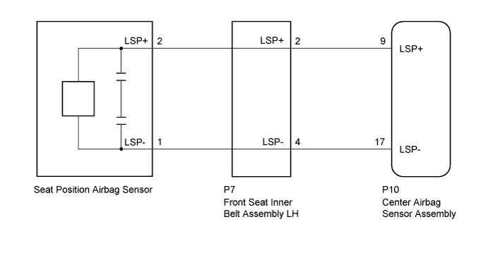
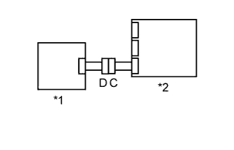
The seat position airbag sensor circuit consists of the center airbag sensor assembly and the seat position airbag sensor.
DTC B1653/35 is recorded when a malfunction is detected in the seat position airbag sensor circuit.
| DTC No. | DTC Detection Condition | Trouble Area |
|---|---|---|
| B1653/35 |
|
|

INSPECTION PROCEDURE
PROCEDURE
- Click here
CHECK VEHICLE CONDITION
-
Check vehicle condition.
Result Result Proceed to for LHD A for RHD B
-
- Click here
CHECK CONNECTORS
-
Turn the engine switch off.
-
Disconnect the cable from the negative (-) battery terminal.
Note:Wait at least 90 seconds after disconnecting the cable from the negative (-) battery terminal to disable the SRS system.
-
Check that the connectors are properly connected to the center airbag sensor assembly, front seat inner belt assembly LH and seat position airbag sensor.
OK The connectors are properly connected. Tip:If the connectors are not connected securely, reconnect the connectors and proceed to the next inspection.
-
Disconnect the connectors from the center airbag sensor assembly, front seat inner belt assembly LH and seat position airbag sensor.
-
Check that the terminals of connectors are not damaged.
OK The terminals are not deformed or damaged.
- OKClick here
- NGClick here
-
- Click here
CHECK SEAT POSITION AIRBAG SENSOR CIRCUIT (OPEN)
-
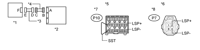
Connect the connectors to the front seat inner belt assembly LH and No. 2 floor wire.
-
Using SST, connect terminals 9 (LSP+) and 17 (LSP-) of connector B.
Note:Do not forcibly insert SST into the terminals of the connector when connecting the wire.
09843-18040 -
Measure the resistance according to the value(s) in the table below.
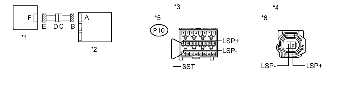
Standard Resistance Tester Connection Condition Specified Condition 2 (LSP+) - 1 (LSP-) Always Below 1 Ω Table 1. Text in Illustration *1 Seat Position Airbag Sensor *2 Center Airbag Sensor Assembly *3 Front view of wire harness connector
(to Center Airbag Sensor Assembly)
*4 Front view of wire harness connector
(to Seat Position Airbag Sensor)
*5 Connector B *6 Connector E
- OKClick here
- NGClick here
-
- Click here
CHECK SEAT POSITION AIRBAG SENSOR CIRCUIT (SHORT)
-
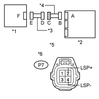
Disconnect SST from connector B.
-
Measure the resistance according to the value(s) in the table below.
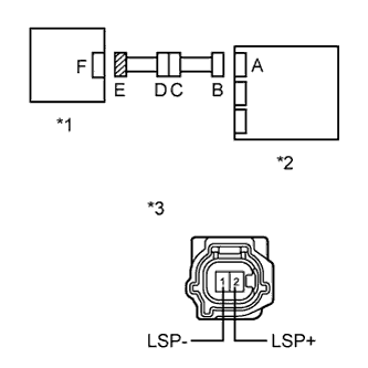
Standard Resistance Tester Connection Condition Specified Condition 2 (LSP+) - 1 (LSP-) Always 1 MΩ or higher Table 2. Text in Illustration *1 Seat Position Airbag Sensor *2 Center Airbag Sensor Assembly *3 Front view of wire harness connector
(to Seat Position Airbag Sensor)
*4 Connector E
- OKClick here
- NGClick here
-
- Click here
CHECK SEAT POSITION AIRBAG SENSOR CIRCUIT (SHORT TO B+)
-
Connect the cable to the negative (-) battery terminal.
-
Turn the engine switch on (IG).
-
Measure the voltage according to the value(s) in the table below.
Standard Voltage Tester Connection Switch Condition Specified Condition 2 (LSP+) - Body ground Engine switch on (IG) Below 1 V 1 (LSP-) - Body ground Engine switch on (IG) Below 1 V Table 3. Text in Illustration *1 Seat Position Airbag Sensor *2 Center Airbag Sensor Assembly *3 Front view of wire harness connector
(to Seat Position Airbag Sensor)
*4 Connector E
- OKClick here
- NGClick here
-
- Click here
CHECK SEAT POSITION AIRBAG SENSOR CIRCUIT (SHORT TO GROUND)
-
Turn the engine switch off.
-
Disconnect the cable from the negative (-) battery terminal.
Note:Wait at least 90 seconds after disconnecting the cable from the negative (-) battery terminal to disable the SRS system.
-
Measure the resistance according to the value(s) in the table below.
Standard Resistance Tester Connection Condition Specified Condition 2 (LSP+) - Body ground Always 1 MΩ or higher 1 (LSP-) - Body ground Always 1 MΩ or higher Table 4. Text in Illustration *1 Seat Position Airbag Sensor *2 Center Airbag Sensor Assembly *3 Front view of wire harness connector
(to Seat Position Airbag Sensor)
*4 Connector E
- OKClick here
- NGClick here
-
- Click here
CHECK SEAT POSITION AIRBAG SENSOR
-
Connect the connectors to the center airbag sensor assembly and seat position airbag sensor.
-
Connect the cable to the negative (-) battery terminal.
-
Turn the engine switch on (IG), and wait for at least 60 seconds.
-
Clear the DTCs stored in the memory (Click here).
-
Turn the engine switch off.
-
Turn the engine switch on (IG), and wait for at least 60 seconds.
-
Check for DTCs (Click here).
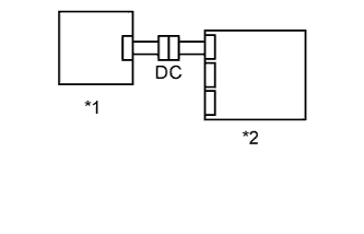
OK DTC B1653/35 is not output. Table 5. Text in Illustration *1 Seat Position Airbag Sensor *2 Center Airbag Sensor Assembly Tip:Codes other than DTC B1653/35 may be output at this time, but they are not related to this check.
- OKClick here
- NGClick here
-
- Click here
REPLACE SEAT POSITION AIRBAG SENSOR
-
Turn the engine switch off.
-
Disconnect the cable from the negative (-) battery terminal.
Note:Wait at least 90 seconds after disconnecting the cable from the negative (-) battery terminal to disable the SRS system.
-
Replace the seat position airbag sensor with a known good part (Click here).
Tip:Perform the following inspection using known good parts from another vehicle if possible.
- NEXTClick here
-
- Click here
CHECK CENTER AIRBAG SENSOR ASSEMBLY
-
Connect the cable to the negative (-) battery terminal.
-
Turn the engine switch on (IG), and wait for at least 60 seconds.
-
Clear the DTCs stored in the memory (Click here).
-
Turn the engine switch off.
-
Turn the engine switch on (IG), and wait for at least 60 seconds.
-
Check for DTCs (Click here).
OK DTC B1653/35 is not output. Table 6. Text in Illustration *1 Seat Position Airbag Sensor *2 Center Airbag Sensor Assembly Tip:Codes other than DTC B1653/35 may be output at this time, but they are not related to this check.
- OKClick here
- NGClick here
-
- Click here
USE SIMULATION METHOD TO CHECKClick here
- Click here
CHECK NO. 2 FLOOR WIRE (OPEN)
-
Disconnect the No. 2 floor wire from the front seat inner belt assembly LH.
Tip:SST has already been inserted into connector B.
-
Measure the resistance according to the value(s) in the table below.
Standard Resistance Tester Connection Condition Specified Condition P7-2 (LSP+) - P7-4 (LSP-) Always Below 1 Ω Table 7. Text in Illustration *1 Seat Position Airbag Sensor *2 Center Airbag Sensor Assembly *3 Front Seat Inner Belt Assembly LH *4 No. 2 Floor Wire *5 Front view of wire harness connector
(to Center Airbag Sensor Assembly)
*6 Front view of wire harness connector
(to Front Seat Inner Belt Assembly LH)
*7 Connector B *8 Connector C
- OKClick here
- NGClick here
-
- Click here
CHECK NO. 2 FLOOR WIRE (SHORT)
-
Disconnect the No. 2 floor wire from the front seat belt inner belt assembly LH.
-
Measure the resistance according to the value(s) in the table below.
Standard Resistance Tester Connection Condition Specified Condition P7-2 (LSP+) - P7-4 (LSP-) Always 1 MΩ or higher Table 8. Text in Illustration *1 Seat Position Airbag Sensor *2 Center Airbag Sensor Assembly *3 Front Seat Inner Belt Assembly LH *4 No. 2 Floor Wire *5 Front view of wire harness connector
(to Front Seat Inner Belt Assembly LH)
*6 Connector C
- OKClick here
- NGClick here
-
- Click here
CHECK NO. 2 FLOOR WIRE (SHORT TO B+)
-
Turn the engine switch off.
-
Disconnect the cable from the negative (-) battery terminal.
Note:Wait at least 90 seconds after disconnecting the cable from the negative (-) battery terminal to disable the SRS system.
-
Disconnect the No. 2 floor wire from the front seat inner belt assembly LH.
-
Connect the cable to the negative (-) battery terminal.
-
Turn the engine switch on (IG).
-
Measure the voltage according to the value(s) in the table below.
Standard Voltage Tester Connection Switch Condition Specified Condition P7-2 (LSP+) - Body ground Engine switch on (IG) Below 1 V P7-4 (LSP-) - Body ground Engine switch on (IG) Below 1 V Table 9. Text in Illustration *1 Seat Position Airbag Sensor *2 Center Airbag Sensor Assembly *3 Front Seat Inner Belt Assembly LH *4 No. 2 Floor Wire *5 Front view of wire harness connector
(to Front Seat Inner Belt Assembly LH)
*6 Connector C
- OKClick here
- NGClick here
-
- Click here
CHECK NO. 2 FLOOR WIRE (SHORT TO GROUND)
-
Disconnect the No. 2 floor wire from the front seat inner belt assembly LH.
-
Measure the resistance according to the value(s) in the table below.
Standard Resistance Tester Connection Condition Specified Condition P7-2 (LSP+) - Body ground Always 1 MΩ or higher P7-4 (LSP-) - Body ground Always 1 MΩ or higher Table 10. Text in Illustration *1 Seat Position Airbag Sensor *2 Center Airbag Sensor Assembly *3 Front Seat Inner Belt Assembly LH *4 No. 2 Floor Wire *5 Front view of wire harness connector
(to Front Seat Inner Belt Assembly LH)
*6 Connector C
- OKClick here
- NGClick here
-
- Click here
REPLACE NO. 2 FLOOR WIRE
- Click here
END
- Click here
REPLACE CENTER AIRBAG SENSOR ASSEMBLYClick here
- Click here
REPLACE FRONT SEAT INNER BELT ASSEMBLY LHClick here
- Click here
REPLACE WIRE HARNESS
- Click here
CHECK CONNECTORS
-
Turn the engine switch off.
-
Disconnect the cable from the negative (-) battery terminal.
Note:Wait at least 90 seconds after disconnecting the cable from the negative (-) battery terminal to disable the SRS system.
-
Check that the connectors are properly connected to the center airbag sensor assembly, front seat inner belt assembly RH and seat position airbag sensor.
OK The connectors are properly connected. Tip:If the connectors are not connected securely, reconnect the connectors and proceed to the next inspection.
-
Disconnect the connectors from the center airbag sensor assembly, front seat inner belt assembly RH and seat position airbag sensor.
-
Check that the terminals of connectors are not damaged.
OK The terminals are not deformed or damaged.
- OKClick here
- NGClick here
-
- Click here
CHECK SEAT POSITION AIRBAG SENSOR CIRCUIT (OPEN)
-
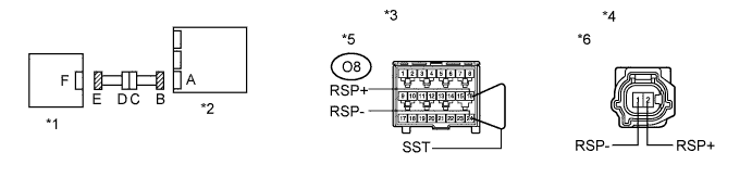
Connect the connectors to the front seat inner belt assembly RH and floor wire.
-
Using SST, connect terminals 16 (RSP+) and 24 (RSP-) of connector B.
Note:Do not forcibly insert SST into the terminals of the connector when connecting the wire.
-
Measure the resistance according to the value(s) in the table below.
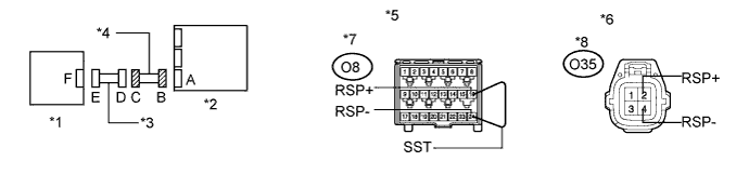
Standard Resistance Tester Connection Condition Specified Condition 2 (RSP+) - 1 (RSP-) Always Below 1 Ω Table 11. Text in Illustration *1 Seat Position Airbag Sensor *2 Center Airbag Sensor Assembly *3 Front view of wire harness connector
(to Center Airbag Sensor Assembly)
*4 Front view of wire harness connector
(to Seat Position Airbag Sensor)
*5 Connector B *6 Connector E
- OKClick here
- NGClick here
-
- Click here
CHECK SEAT POSITION AIRBAG SENSOR CIRCUIT (SHORT)
-
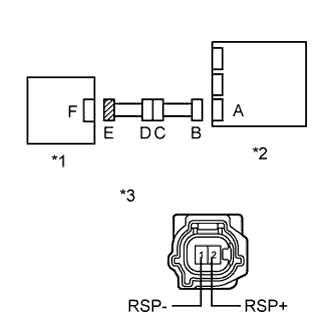
Disconnect SST from connector B.
-
Measure the resistance according to the value(s) in the table below.
Standard Resistance Tester Connection Condition Specified Condition 2 (RSP+) - 1 (RSP-) Always 1 MΩ or higher Table 12. Text in Illustration *1 Seat Position Airbag Sensor *2 Center Airbag Sensor Assembly *3 Front view of wire harness connector
(to Seat Position Airbag Sensor)
*4 Connector E
- OKClick here
- NGClick here
-
- Click here
CHECK SEAT POSITION AIRBAG SENSOR CIRCUIT (SHORT TO B+)
-
Connect the cable to the negative (-) battery terminal.
-
Turn the engine switch on (IG).
-
Measure the voltage according to the value(s) in the table below.
Standard Voltage Tester Connection Switch Condition Specified Condition 2 (RSP+) - Body ground Engine switch on (IG) Below 1 V 1 (RSP-) - Body ground Engine switch on (IG) Below 1 V Table 13. Text in Illustration *1 Seat Position Airbag Sensor *2 Center Airbag Sensor Assembly *3 Front view of wire harness connector
(to Seat Position Airbag Sensor)
*4 Connector E
- OKClick here
- NGClick here
-
- Click here
CHECK SEAT POSITION AIRBAG SENSOR CIRCUIT (SHORT TO GROUND)
-
Turn the engine switch off.
-
Disconnect the cable from the negative (-) battery terminal.
Note:Wait at least 90 seconds after disconnecting the cable from the negative (-) battery terminal to disable the SRS system.
-
Measure the resistance according to the value(s) in the table below.
Standard Resistance Tester Connection Condition Specified Condition 2 (RSP+) - Body ground Always 1 MΩ or higher 1 (RSP-) - Body ground Always 1 MΩ or higher Table 14. Text in Illustration *1 Seat Position Airbag Sensor *2 Center Airbag Sensor Assembly *3 Front view of wire harness connector
(to Seat Position Airbag Sensor)
*4 Connector E
- OKClick here
- NGClick here
-
- Click here
CHECK SEAT POSITION AIRBAG SENSOR
-
Connect the connectors to the center airbag sensor assembly and seat position airbag sensor.
-
Connect the cable to the negative (-) battery terminal.
-
Turn the engine switch on (IG), and wait for at least 60 seconds.
-
Clear the DTCs stored in the memory (Click here).
-
Turn the engine switch off.
-
Turn the engine switch on (IG), and wait for at least 60 seconds.
-
Check for DTCs (Click here).
OK DTC B1653/35 is not output. Table 15. Text in Illustration *1 Seat Position Airbag Sensor *2 Center Airbag Sensor Assembly Tip:Codes other than DTC B1653/35 may be output at this time, but they are not related to this check.
- OKClick here
- NGClick here
-
- Click here
REPLACE SEAT POSITION AIRBAG SENSOR
-
Turn the engine switch off.
-
Disconnect the cable from the negative (-) battery terminal.
Note:Wait at least 90 seconds after disconnecting the cable from the negative (-) battery terminal to disable the SRS system.
-
Replace the seat position airbag sensor with a known good part (Click here).
Tip:Perform the following inspection using known good parts from another vehicle if possible.
- NEXTClick here
-
- Click here
CHECK CENTER AIRBAG SENSOR ASSEMBLY
-
Connect the cable to the negative (-) battery terminal.
-
Turn the engine switch on (IG), and wait for at least 60 seconds.
-
Clear the DTCs stored in the memory (Click here).
-
Turn the engine switch off.
-
Turn the engine switch on (IG), and wait for at least 60 seconds.
-
Check for DTCs (Click here).
OK DTC B1653/35 is not output. Table 16. Text in Illustration *1 Seat Position Airbag Sensor *2 Center Airbag Sensor Assembly Tip:Codes other than DTC B1653/35 may be output at this time, but they are not related to this check.
- OKClick here
- NGClick here
-
- Click here
CHECK FLOOR WIRE (OPEN)
-
Disconnect the floor wire from the front seat inner belt assembly RH.
Tip:SST has already been inserted into connector B.
-
Measure the resistance according to the value(s) in the table below.
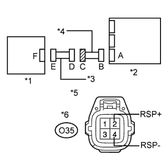
Standard Resistance Tester Connection Condition Specified Condition O35-2 (RSP+) - O35-4 (RSP-) Always Below 1 Ω Table 17. Text in Illustration *1 Seat Position Airbag Sensor *2 Center Airbag Sensor Assembly *3 Front Seat Inner Belt Assembly RH *4 Floor Wire *5 Front view of wire harness connector
(to Center Airbag Sensor Assembly)
*6 Front view of wire harness connector
(to Front Seat Inner Belt Assembly RH)
*7 Connector B *8 Connector C
- OKClick here
- NGClick here
-
- Click here
CHECK FLOOR WIRE (SHORT)
-
Disconnect the floor wire from the front seat belt inner belt assembly RH.
-
Measure the resistance according to the value(s) in the table below.
Standard Resistance Tester Connection Condition Specified Condition O35-2 (RSP+) - O35-4 (RSP-) Always 1 MΩ or higher Table 18. Text in Illustration *1 Seat Position Airbag Sensor *2 Center Airbag Sensor Assembly *3 Front Seat Inner Belt Assembly RH *4 Floor Wire *5 Front view of wire harness connector
(to Front Seat Inner Belt Assembly RH)
*6 Connector C
- OKClick here
- NGClick here
-
- Click here
CHECK FLOOR WIRE (SHORT TO B+)
-
Turn the engine switch off.
-
Disconnect the cable from the negative (-) battery terminal.
Note:Wait at least 90 seconds after disconnecting the cable from the negative (-) battery terminal to disable the SRS system.
-
Disconnect the floor wire from the front seat inner belt assembly RH.
-
Connect the cable to the negative (-) battery terminal.
-
Turn the engine switch on (IG).
-
Measure the voltage according to the value(s) in the table below.
Standard Voltage Tester Connection Switch Condition Specified Condition O35-2 (RSP+) - Body ground Engine switch on (IG) Below 1 V O35-4 (RSP-) - Body ground Engine switch on (IG) Below 1 V Table 19. Text in Illustration *1 Seat Position Airbag Sensor *2 Center Airbag Sensor Assembly *3 Front Seat Inner Belt Assembly RH *4 Floor Wire *5 Front view of wire harness connector
(to Front Seat Inner Belt Assembly RH)
*6 Connector C
- OKClick here
- NGClick here
-
- Click here
CHECK FLOOR WIRE (SHORT TO GROUND)
-
Disconnect the floor wire from the front seat inner belt assembly RH.
-
Measure the resistance according to the value(s) in the table below.
Standard Resistance Tester Connection Condition Specified Condition O35-2 (RSP+) - Body ground Always 1 MΩ or higher O35-4 (RSP-) - Body ground Always 1 MΩ or higher Table 20. Text in Illustration *1 Seat Position Airbag Sensor *2 Center Airbag Sensor Assembly *3 Front Seat Inner Belt Assembly RH *4 Floor Wire *5 Front view of wire harness connector
(to Front Seat Inner Belt Assembly RH)
*6 Connector C
- OKClick here
- NGClick here
-
- Click here
REPLACE FRONT SEAT INNER BELT ASSEMBLY RHClick here
- Click here
REPLACE FLOOR WIRE