COMBINATION METER REMOVAL

-
PRECAUTION
Note
After turning the engine switch off, waiting time may be required before disconnecting the cable from the negative (-) battery terminal. Therefore, make sure to read the disconnecting the cable from the negative (-) battery terminal notices before proceeding with work Click here.
-
DISCONNECT CABLE FROM NEGATIVE BATTERY TERMINAL
-
Disable the auto tilt away function by changing the customize parameter Click here.
Note
Record the current customize parameter setting (whether the auto tilt away function is enabled or disabled) in order to restore the current setting after finishing this operation.
Tech Tips
Performing the above operation disables the auto tilt away function when the engine switch is turned off.
-
Turn the engine switch on (IG). Operate the tilt and telescopic switch to fully extend and lower the steering column assembly.
-
Turn the engine switch off and disconnect the cable from the negative (-) battery terminal.
Note
When disconnecting the cable, some systems need to be initialized after the cable is reconnected Click here.
-
-
REMOVE INSTRUMENT PANEL GARNISH LH
-
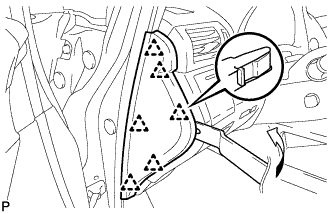
Using moulding remover B, disengage the 6 clips and remove the instrument panel garnish LH as shown in the illustration.
-
-
REMOVE NO. 1 SWITCH HOLE BASE
-
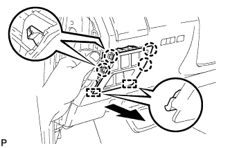
Push the No. 1 switch hole base in the direction indicated by the arrow to disengage the 4 claws and 2 guides.
-
Disconnect each connector and remove the No. 1 switch hole base.
-
-
REMOVE LOWER INSTRUMENT PANEL FINISH PANEL SUB-ASSEMBLY
-
Disengage the 2 claws and open the cover as shown in the illustration.
-
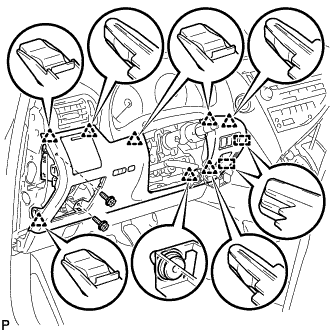
Remove the 2 screws <D>.
-
Disengage the 8 clips and 2 guides.
-
Disconnect each connector and remove the lower instrument panel finish panel sub-assembly.
-
-
REMOVE NO. 1 INSTRUMENT PANEL HOLE COVER
-
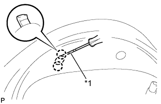
Text in Illustration *1 Protective Tape Using a screwdriver, disengage the 2 claws and remove the No. 1 instrument panel hole cover.
Tech Tips
Tape the screwdriver tip before use.
-
-
REMOVE NO. 2 INSTRUMENT PANEL HOLE COVER
Tech Tips
Use the same procedure as for the No. 1 instrument panel hole cover.
-
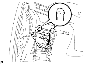
REMOVE NO. 1 INSTRUMENT CLUSTER FINISH PANEL
-
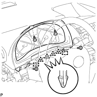
Remove the 2 clips and 2 screws.
-
Disengage the 4 clips and 2 guides, and remove the No. 1 instrument cluster finish panel.
-
-
REMOVE COMBINATION METER ASSEMBLY
-
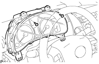
Remove the 2 screws.
-
Disconnect each connector and remove the combination meter assembly.
-