METER / GAUGE SYSTEM Headup Display Malfunction
DESCRIPTION
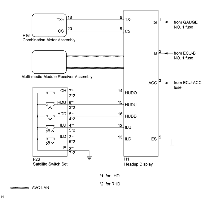
This circuit is the power source circuit for the headup display. This circuit provides two types of power sources; one is a constant power source mainly used as a backup power source, and the other is a power source mainly used for signal transmission.
WIRING DIAGRAM
INSPECTION PROCEDURE
Tech Tips
Before starting the following inspection, confirm the headup display position illuminance, then perform the on-vehicle inspection Click here.
PROCEDURE
-
SYSTEM CHECK
-
Check the symptom of the headup display.
Result Result Proceed to Headup display does not operate at all. A Cruise information display does not change. B
B 
CHECK HARNESS AND CONNECTOR (COMBINATION METER ASSEMBLY - HEADUP DISPLAY) Click here
A 
-
-
CHECK HARNESS AND CONNECTOR (HEADUP DISPLAY CIRCUIT)
-
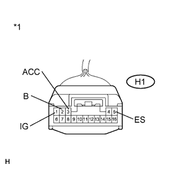
Text in Illustration *1 Front view of wire harness connector
(to Headup Display)
Disconnect the H1 connector.
-
Measure the voltage according to the value(s) in the table below.
Standard Voltage Tester Connection Condition Specified Condition H1-1 (IG) - Body ground Engine switch on (IG) 11 to 14 V H1-2 (B) - Body ground Always 11 to 14 V H1-3 (ACC) - Body ground Engine switch on (ACC) 11 to 14 V -
Measure the resistance according to the value(s) in the table below
Standard Resistance Tester Connection Condition Specified Condition H1-5 (ES) - Body ground Always Below 1 Ω
NG 
REPAIR OR REPLACE HARNESS OR CONNECTOR
OK
-
-
CHECK HARNESS AND CONNECTOR (HEADUP DISPLAY - SATELLITE SWITCH SET)
-
for LHD
-
Disconnect the H1 and F23 connectors.
-
Measure the resistance according to the value(s) in the table below.
Standard Resistance Tester Connection Condition Specified Condition H1-14 (HUDO) - F23-7 (CH) Always Below 1 Ω H1-14 (HUDO) - Body ground Always 10 kΩ or higher H1-15 (HUDU) - F23-6 (HDU) Always Below 1 Ω H1-15 (HUDU) - Body ground Always 10 kΩ or higher H1-16 (HUDD) - F23-5 (HDD) Always Below 1 Ω H1-16 (HUDD) - Body ground Always 10 kΩ or higher H1-12 (ILU) - F23-4 (ILU) Always Below 1 Ω H1-12 (ILU) - Body ground Always 10 kΩ or higher H1-13 (ILD) - F23-3 (ILD) Always Below 1 Ω H1-13 (ILD) - Body ground Always 10 kΩ or higher
-
-
for RHD
-
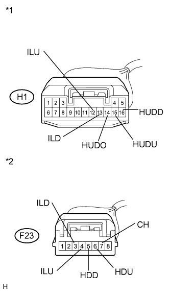
Text in Illustration *1 Front view of wire harness connector
(to Headup Display)
*2 Front view of wire harness connector
(to Satellite Switch Set)
Disconnect the H1 and F23 connectors.
-
Measure the resistance according to the value(s) in the table below.
Standard Resistance Tester Connection Condition Specified Condition H1-14 (HUDO) - F23-2 (CH) Always Below 1 Ω H1-14 (HUDO) - Body ground Always 10 kΩ or higher H1-15 (HUDU) - F23-3 (HDU) Always Below 1 Ω H1-15 (HUDU) - Body ground Always 10 kΩ or higher H1-16 (HUDD) - F23-4 (HDD) Always Below 1 Ω H1-16 (HUDD) - Body ground Always 10 kΩ or higher H1-12 (ILU) - F23-5 (ILU) Always Below 1 Ω H1-12 (ILU) - Body ground Always 10 kΩ or higher H1-13 (ILD) - F23-6 (ILD) Always Below 1 Ω H1-13 (ILD) - Body ground Always 10 kΩ or higher
-
NG
REPAIR OR REPLACE HARNESS OR CONNECTOR
OK
-
-
INSPECT SATELLITE SWITCH SET
-
for LHD
-
Disconnect the H1 connector.
-
Measure the resistance according to the value(s) in the table below.
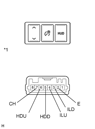
Standard Resistance Tester Connection Switch Condition Specified Condition 2 (E) - 3 (ILD) Display contrast down switch pressed Below 1 Ω 2 (E) - 3 (ILD) Display contrast down switch not pressed 10 kΩ or higher 2 (E) - 4 (ILU) Display contrast up switch pressed Below 1 Ω 2 (E) - 4 (ILU) Display contrast up switch not pressed 10 kΩ or higher 2 (E) - 5 (HDD) Headup display position down switch pressed Below 1 Ω 2 (E) - 5 (HDD) Headup display position down switch not pressed 10 kΩ or higher 2 (E) - 6 (HDU) Headup display position up switch pressed Below 1 Ω 2 (E) - 6 (HDU) Headup display position up switch not pressed 10 kΩ or higher 2 (E) - 7 (CH) Headup display on switch pressed Below 1 Ω 2 (E) - 7 (CH) Headup display on switch not pressed 10 kΩ or higher
-
-
for RHD
-
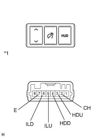
Text in Illustration *1 Component without harness connected
(Satellite Switch Set)
Disconnect the H1 connector.
-
Measure the resistance according to the value(s) in the table below.
Standard Resistance Tester Connection Switch Condition Specified Condition 6 (ILD) - 7 (E) Display contrast down switch pressed Below 1 Ω 6 (ILD) - 7 (E) Display contrast down switch not pressed 10 kΩ or higher 5 (ILU) - 7 (E) Display contrast up switch pressed Below 1 Ω 5 (ILU) - 7 (E) Display contrast up switch not pressed 10 kΩ or higher 4 (HDD) - 7 (E) Headup display position down switch pressed Below 1 Ω 4 (HDD) - 7 (E) Headup display position down switch not pressed 10 kΩ or higher 3 (HDU) - 7 (E) Headup display position up switch pressed Below 1 Ω 3 (HDU) - 7 (E) Headup display position up switch not pressed 10 kΩ or higher 2 (CH) - 7 (E) Headup display on switch pressed Below 1 Ω 2 (CH) - 7 (E) Headup display on switch not pressed 10 kΩ or higher
-
NG
REPLACE SATELLITE SWITCH SET Click here
OK 
REPLACE HEADUP DISPLAY Click here
-
-
CHECK HARNESS AND CONNECTOR (COMBINATION METER ASSEMBLY - HEADUP DISPLAY)
-
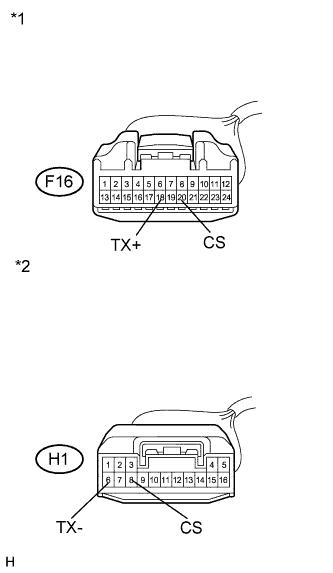
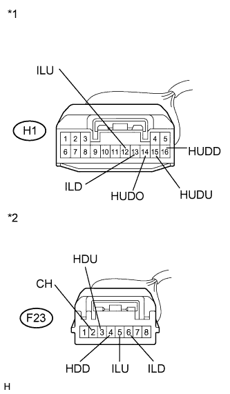
Text in Illustration *1 Front view of wire harness connector
(to Combination Meter Assembly)
*2 Front view of wire harness connector
(to Headup Display)
Disconnect the F16 and H1 connectors.
-
Disconnect the H1 connector.
-
Measure the resistance according to the value(s) in the table below.
Standard Resistance Tester Connection Condition Specified Condition F16-18 (TX+) - H1-6 (TX- ) Always Below 1 Ω F16-18 (TX+) - Body ground Always 10 kΩ or higher F16-20 (CS) - H1-8 (CS) Always Below 1 Ω F16-20 (CS) - Body ground Always 10 kΩ or higher
NG
REPAIR OR REPLACE HARNESS OR CONNECTOR
OK
-
-
REPLACE HEADUP DISPLAY
-
Replace the headup display with a new or a known good one Click here.
OK The operation of the headup display returns to normal.
NG
REPLACE COMBINATION METER ASSEMBLY Click here
OK
END
-