METER / GAUGE SYSTEM TERMINALS OF ECU

-
COMBINATION METER ASSEMBLY
-
Measure the voltage and resistance according to the value(s) in the table below.
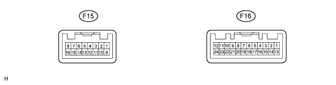
Terminal No. (Symbol) Wiring Color Terminal Description Condition Specified Condition F15-1 (B) - Body ground V - Body ground Turn indicator light signal Engine switch on (IG), turn LH indicator light off Below 1 V Engine switch on (IG), turn LH indicator light blinks Below 1 V ←→ 11 to 14 V F15-3 (+S) - Body ground LG - Body ground Speed signal for other systems (Output) Engine switch on (IG), front wheel turns slowly Pulse generation
(See waveform 1)
F15-4 (SI) - Body ground BR - Body ground Speed signal for other systems (Input) Engine switch on (IG), front wheel turns slowly Pulse generation
(See waveform 1)
F15-5 (S) - Body ground Y - Body ground Oil pressure switch signal Engine switch on (IG), oil pressure warning display off 11 to 14 V Engine switch on (IG), oil pressure warning display comes on Below 1 V F15-6 (OIL)*1 - Body ground R - Body ground Oil level sensor signal Engine switch on (IG), oil level warning display off 11 to 14 V Engine switch on (IG), oil level warning display comes on Below 1 V F15-7 (WLVL) - Body ground L - Body ground Washer level warning switch signal Engine switch on (IG), washer level warning display off 11 to 14 V Engine switch on (IG), washer level warning display comes on Below 1 V F15-8 (B/LE) - Body ground W - Body ground Brake fluid level warning light signal Engine switch on (IG), brake fluid level warning light off 11 to 14 V Engine switch on (IG), brake fluid level warning light on Below 1 V F15-10 (P/SB) - Body ground L*4 - Body ground
GR*5 - Body ground
Front passenger side seat belt buckle switch signal Engine switch on (IG), sit on the front passenger seat, and front passenger side seat belt unfastened Below 1 V ←→ 11 to 14 V Engine switch on (IG), sit on the front passenger seat, and front passenger side seat belt fastened Below 1 V F15-11 (CHG-) - Body ground G - Body ground Charge warning light signal Engine switch on (IG), charge warning light off 11 to 14 V Engine switch on (IG), oil pressure warning light on Below 1 V F15-12 (RRSB)*2 - Body ground P - Body ground Rear RH passenger seat belt buckle switch signal Engine switch on (IG), rear RH passenger seat belt unfastened Below 1 V Engine switch on (IG), rear RH passenger seat belt fastened 11 to 14 V F15-13 (RCSB)*2 - Body ground SB - Body ground Rear center passenger seat belt buckle switch signal Engine switch on (IG), rear center passenger seat belt unfastened Below 1 V Engine switch on (IG), rear center passenger seat belt fastened 11 to 14 V F15-14 (RLSB)*2 - Body ground B - Body ground Rear left passenger seat belt buckle switch signal Engine switch on (IG), rear left passenger seat belt unfastened Below 1 V Engine switch on (IG), rear left passenger seat belt fastened 11 to 14 V F15-15 (ILL-) - Body ground BE - Body ground Illumination signal Light control switch off Below 1 V Light control switch in tail or head position Pulse generation F15-16 (E2) - Body ground W-B - Body ground Ground (Signal ground) Always Below 1 V F16-1 (IG+) - Body ground GR - Body ground Engine switch signal Engine switch off Below 1 V Engine switch on (IG) 11 to 14 V F16-2 (B) - Body ground LG - Body ground Turn indicator light signal Engine switch on (IG), turn RH indicator light off Below 1 V Engine switch on (IG), turn RH indicator light blinks Below 1 V ←→ 11 to 14 V F16-4 (MSSL) - Body ground Y - Body ground Steering pad switch assembly signal (Menu, ENTER, Up, or Down switch) Engine switch on (IG), Menu, ENTER, Up, or Down switch pressed Below 1 V Engine switch on (IG), Menu, ENTER, Up, or Down switch not pressed 11 to 14 V F16-5 (ET) - Body ground V - Body ground Ground Always Below 1 V F16-6 (ES) - Body ground W-B - Body ground Ground Always Below 1 V F16-7 (RHUP) - Body ground GR - Body ground Light control rheostat signal (Light control rheostat up switch) Engine switch on (IG), up switch pressed Below 1 V Engine switch on (IG), up switch not pressed 11 to 14 V F16-8 (RHDW) - Body ground Y - Body ground Light control rheostat signal (Light control rheostat down switch) Engine switch on (IG), down switch pressed Below 1 V Engine switch on (IG), down switch not pressed 11 to 14 V F16-9 (A/B) - Body ground W - Body ground Light control rheostat signal (ODO/TRIP change switch) Engine switch on (IG), ODO/TRIP change switch pressed Below 1 V Engine switch on (IG), ODO/TRIP change switch not pressed 4 to 6 V F16-12 (PBLT) - Body ground L - Body ground Front passenger side seat belt warning light signal Engine switch on (IG), front passenger side seat belt warning light off 11 to 14 V Engine switch on (IG), front passenger side seat belt warning light blinks Below 1 V ←→ 11 to 14 V F16-13 (B) - Body ground SB - Body ground Engine switch signal Always 11 to 14 V F16-16 (FR) - Body ground G - Body ground Fuel level signal Engine switch on (IG), fuel level warning light off Below 4 V Engine switch on (IG), fuel level warning light on 4 to 9 V F16-17 (FE) - Body ground SB - Body ground Ground (Fuel ground) Always Below 1 V F16-18 (TX+)*3 - Body ground W - Body ground Headup display communication signal Always Pulse generation F16-20 (CS)*3 - Body ground BE - Body ground Headup display communication signal Always Below 1 V F16-21 (CHK) - Body ground BR - Body ground MIL (Check engine warning light) signal Engine switch on (IG), MIL (Check engine warning light) off 11 to 14 V Engine switch on (IG), slip indicator light comes on Below 1 V F16-23 (CANH) - Body ground P - Body ground CAN communication signal Engine switch off 200 Ω or higher F16-24 (CANL) - Body ground R - Body ground CAN communication signal Engine switch off 200 Ω or higher
-
*1: w/ Oil Level Sensor
-
*2: w/ Rear Seat Belt Warning
-
*3: w/ Headup Display
-
*4: for LHD
-
*5: for RHD
-
-
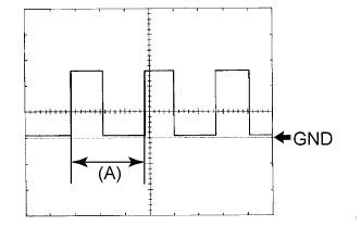
Waveform 1 (Reference): Using an oscilloscope:
Item Condition Tool setting 5 V/DIV., 20 ms./DIV. Vehicle condition Driving at approx. 20 km/h (12 mph) Tech Tips
When the system is functioning normally, one wheel revolution generates 4 pulses. As the vehicle speed increases, the width indicated by (A) in the illustration narrows.
Terminal No. (Symbol) Wire Harness Side F15 1 (B) Turn Signal Flasher 2 - 3 (+S) Each part that uses the vehicle speed signal 4 (SI) Skid Control ECU 5 (S) Oil Pressure Switch 6 (OIL) Oil Level Sensor*1 7 (WLVL) Washer Fluid Level Warning Switch 8 (B/LE) Brake Fluid Level Warning Switch 9 - 10 (P/SB) Front Passenger Side Seat Belt Buckle Switch 11 (CHG-) Generator 12 (RRSB) Rear RH Passenger Seat Belt Buckle Switch*2 13 (RCSB) Rear Center Passenger Seat Belt Buckle Switch*2 14 (RLSB) Rear LH Passenger Seat Belt Buckle Switch*2 15 (ILL-) Each part that uses the illumination signal 16 (E2) Ground F16 1 (IG+) GAUGE NO. 2 Fuse 2 (B) Turn Signal Flasher 3 - 4 (MSSL) Multi-information Switch (Steering Pad Switch Assembly) 5 (ET) Ground 6 (ES) Ground 7 (RHUP) Light Control Rheostat (Light Control Rheostat Up Switch) 8 (RHDW) Light Control Rheostat (Light Control Rheostat Down Switch) 9 (A/B) Light Control Rheostat (ODO/TRIP Switch) 10 - 11 - 12 (PBLT) Multi-media Module Receiver Assembly*4 or Radio Receiver Assembly*5 13 (B) ECU-B NO. 1 Fuse 14 - 15 - 16 (FR) Fuel Sender Gauge Assembly 17 (FE) Fuel Sender Gauge Assembly 18 (TX+) Headup Display*3 19 - 20 (CS) Headup Display*3 21 (CHK) ECM 22 - 23 (CANH) CAN Communication Line 24 (CANL) CAN Communication Line
-
*1: w/ Oil Level Sensor
-
*2: w/ Rear Seat Belt Warning
-
*3: w/ Headup Display
-
*4: w/ Navigation System
-
*5: w/o Navigation System
-
-
-
ACCESSORY METER ASSEMBLY (w/o Multi-display)

-
Measure the voltage and resistance according to the value(s) in the table below.
Terminal No. (Symbol) Wiring Color Terminal Description Condition Specified Condition G1-1 (IG+) - Body ground W - Body ground Engine switch signal Engine switch off Below 1 V Engine switch on (IG) 11 to 14 V G1-2 (IG2) - Body ground LG - Body ground Engine switch signal Engine switch off Below 1 V Engine switch on (IG) 11 to 14 V G1-3 (ACC) - Body ground W - Body ground Engine switch signal Engine switch off Below 1 V Engine switch on (IG) 11 to 14 V G1-6 (PBEW) - Body ground L - Body ground Front passenger side seat belt warning light signal Engine switch on (IG), front passenger side seat belt warning light off 11 to 14 V Engine switch on (IG), front passenger side seat belt warning light blinks Below 1 V ←→ 11 to 14 V G1-7 (P-AB) - Body ground BR - Body ground Front passenger side airbag OFF indicator light signal Engine switch on (IG), front passenger side airbag OFF indicator light off Below 1 V Engine switch on (IG), front passenger side airbag OFF indicator light on 11 to 14 V G1-8 (PAON) - Body ground G - Body ground Front passenger side airbag ON indicator light signal Engine switch on (IG), front passenger side airbag ON indicator light off Below 1 V Engine switch on (IG), front passenger side airbag ON indicator light on 11 to 14 V G1-10 (TX2+) - Body ground P - Body ground AVC-LAN communication signal Always Below 1 V G1-12 (GND1) - Body ground W-B - Body ground Ground Always Below 1 Ω G1-13 (+B) - Body ground GR - Body ground Battery Always 11 to 14 V G1-14 (ADIM) - Body ground P - Body ground Auto dimmer signal Engine switch on (IG), light control switch off Below 1 V Engine switch on (IG), light control switch in tail, head, or AUTO position at night 4 to 6 V G1-17 (CLK2) - Body ground R - Body ground Clock adjust switch signal H, M or light control adjust switch not pressed 11 to 14 V H, M or light control adjust switch pressed Below 1 V G1-18 (CLK4) - Body ground B - Body ground Clock adjust switch signal H, M or light control adjust switch not pressed 11 to 14 V H, M or light control adjust switch pressed Below 1 V G1-20 (LIN1) - Body ground SB - Body ground LIN communication signal Engine switch on (IG) Pulse generation G1-22 (TX2-) - Body ground L - Body ground AVC-LAN communication signal Always 11 to 14 V G1-24 (ILL-) - Body ground R - Body ground Illumination signal Light control switch off Below 1 V Light control switch in tail or head position 11 to 14 V Terminal No. (Symbol) Wire Harness Side G1 1 (IG+) GAUGE NO. 1 2 (IG2) GAUGE NO. 1 Fuse 3 (ACC) ECU-ACC Fuse 4 - 5 - 6 (PBEW) Combination Meter Assembly 7 (P-AB) Center Airbag Sensor Assembly 8 (PAON) Center Airbag Sensor Assembly 9 - 10 (TX2+) Radio Receiver Assembly (for Radio Receiver Type) 11 - 12 (GND1) Ground 13 (+B) Battery 14 (ADIM) Main Body ECU (Multiplex Network Body ECU) 15 - 16 - 17 (CLK2) Radio Receiver Assembly (for Radio Receiver Type) 18 (CLK4) Radio Receiver Assembly (for Radio Receiver Type) 19 - 20 (LIN1) Air Conditioning Amplifier 21 - 22 (TX2-) Radio Receiver Assembly (for Radio Receiver Type) 23 - 24 (ILL-) Combination Meter Assembly
-
-
HEADUP DISPLAY (w/ Headup Display)
-
Measure the voltage and resistance according to the value(s) in the table below.

Terminal No. (Symbol) Wiring Color Terminal Description Condition Specified Condition H1-1 (IG) - Body ground W - Body ground Engine switch signal Engine switch off Below 1 V Engine switch on (IG) 11 to 14 V H1-2 (B) - Body ground SB - Body ground Battery Always 11 to 14 V H1-3 (ACC) - Body ground GR - Body ground Engine switch signal Engine switch off Below 1 V Engine switch on (ACC) 11 to 14 V H1-5 (ES) - Body ground W-B - Body ground Ground Always Below 1 Ω H1-6 (TX-) - Body ground B - Body ground AVC-LAN communication signal Always Pulse generation H1-8 (CS) - Body ground BR - Body ground LIN communication signal Always Pulse generation H1-10 (MPX1) - Body ground G - Body ground Multiplex communication signal Engine switch on (IG) Pulse generation H1-11 (MPX2) - Body ground R - Body ground Multiplex communication signal Engine switch on (IG) Pulse generation H1-12 (ILU) - Body ground LG - Body ground Satellite switch signal (Display contrast up switch) Engine switch on (IG), headup display contrast up switch not pressed 11 to 14 V Engine switch on (IG), headup display contrast up switch pressed Below 1 V H1-13 (ILD) - Body ground L - Body ground Satellite switch signal (Display contrast down switch) Engine switch on (IG), headup display contrast down switch not pressed 11 to 14 V Engine switch on (IG), headup display contrast down switch pressed Below 1 V H1-14 (HUDO) - Body ground Y - Body ground Satellite switch signal (Headup display on switch) Engine switch on (IG), headup display on switch not pressed Below 1 V Engine switch on (IG), headup display on switch pressed 11 to 14 V H1-15 (HUDU) - Body ground V - Body ground Satellite switch signal (Headup display position up switch) Engine switch on (IG), headup display position up switch not pressed Below 1 V Engine switch on (IG), headup display position up switch pressed 11 to 14 V H1-16 (HUDD) - Body ground P - Body ground Satellite switch signal (Headup display position down switch) Engine switch on (IG), headup display position down switch not pressed Below 1 V Engine switch on (IG), headup display position down switch pressed 11 to 14 V Terminal No. (Symbol) Wire Harness Side H1 1 (IG) GAUGE NO. 1 Fuse 2 (B) ECU-B NO. 1 Fuse 3 (ACC) ECU-ACC Fuse 4 - 5 (ES) Ground 6 (TX-) Combination Meter Assembly 7 - 8 (CS) Combination Meter Assembly 9 - 10 (MPX1) Multi-media Module Receiver Assembly 11 (MPX2) Multi-media Module Receiver Assembly 12 (ILU) Satellite Switch Set (Headup display contrast up switch) 13 (ILD) Satellite Switch Set (Headup display contrast down switch) 14 (HUDO) Satellite Switch Set (Headup display on switch) 15 (HUDU) Satellite Switch Set (Headup display position up switch) 16 (HUDD) Satellite Switch Set (Headup display position down switch)
-