METER / GAUGE SYSTEM SYSTEM DESCRIPTION

-
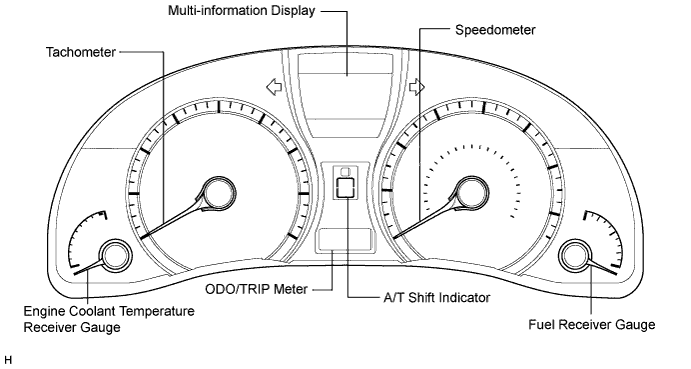
OUTLINE OF COMBINATION METER ASSEMBLY
-
Meter or Gauge
Item Detail Speedometer Indicates the vehicle speed based on a signal received from the skid control ECU via the CAN communication system (CAN No. 1 Bus). Tachometer Indicates the engine speed based on a signal received from the ECM via the CAN communication system (CAN No. 1 Bus). Fuel Receiver Gauge Indicates the fuel level based on a signal received from the fuel sender gauge assembly via the direct line. Engine Coolant Temperature Receiver Gauge Indicates the engine coolant temperature based on a signal received from the ECM via the CAN communication system (CAN No. 1 Bus). -
Warning Light or Indicator Light
Item Detail High Beam Receives a high beam indicator light signal from the main body ECU (multiplex network body ECU) via the CAN communication system (CAN No. 1 Bus). Turn Receives a turn indicator signal from the turn signal flasher via the direct line. Fuel level Receives a fuel signal from the fuel sender gauge assembly via the direct line. Brake Receives a brake signal from the brake fluid level warning switch via the direct line and the skid control ECU via the CAN communication system (CAN No. 1 Bus). SRS Receives an SRS signal from the center airbag sensor assembly via the CAN communication system (CAN No. 1 Bus). Open door Receives a door condition signal from the main body ECU (multiplex network body ECU) via the CAN communication system (CAN No. 1 Bus). Charge Receives a charge indicator light signal from the generator via the direct line. MIL (Check engine warning light) Receives a MIL (check engine warning light) signal from the ECM via the direct line. Driver side seat belt Receives a driver side seat belt signal from the main body ECU (multiplex network body ECU) via the CAN communication system (CAN No. 1 Bus). ABS Receives an ABS signal from the skid control ECU via the CAN communication system (CAN No. 1 Bus). EPS Receives an EPS signal from the power steering ECU via the CAN communication system (CAN No. 1 Bus). Air suspension*1 Receives an air suspension signal from the suspension control ECU via the CAN communication system (CAN No. 2 Bus). Luggage mode*1 Receives a luggage mode signal from the suspension control ECU via the CAN communication system (CAN No. 2 Bus). Tail Receives a tail signal from the main body ECU (multiplex network body ECU) via the CAN communication system (CAN No. 1 Bus). AWD lock*9 Receives an AWD lock signal from the AWD control ECU via the CAN communication system (CAN No. 2 Bus). VSC OFF Receives a VSC OFF signal from the skid control ECU via the CAN communication system (CAN No. 1 Bus). ECO driving Receives an ECO driving signal from the ECM via the CAN communication system (CAN No. 1 Bus). ECT snow*2 Receives an ECT snow signal from the ECM via the CAN communication system (CAN No. 1 Bus). PCS*3 Receives a PCS signal from the driving support ECU assembly via the CAN communication system (CAN No. 2 Bus). Cruise main*4 Receives a cruise main (constant speed control mode or vehicle-to-vehicle distance control mode) signal from the driving support ECU assembly via the CAN communication system (CAN No. 2 Bus). Slip Receives a slip signal from the skid control ECU via the CAN communication system (CAN No. 1 Bus). Cruise main Receives a cruise signal from the ECM via the CAN communication system (CAN No. 1 Bus). A/T shift Receives an A/T shift condition signal from the park/neutral position switch (direct line)*7 and the ECM via the CAN communication system (CAN No. 1 Bus). Clearance sonar*5 Receives a clearance sonar signal from the clearance warning ECU via the CAN communication system (CAN No. 2 Bus). AFS OFF*6 Receives an AFS OFF signal from the AFS ECU (headlight swivel ECU assembly) via the CAN communication system (CAN No. 2 Bus). Front fog Receives a front fog signal from the main body ECU (multiplex network body ECU) via the CAN communication system (CAN No. 1 Bus). Rear fog*7 Receives a rear fog signal from the main body ECU (multiplex network body ECU) via the CAN communication system (CAN No. 1 Bus). Front passenger side seat belt warning light Receives a front passenger side seat belt buckle switch signal from the front passenger side seat belt buckle switch via the direct line. Master warning Comes on when the reminder message or warning message appears on the multi-information display. Tire Pressure*8 Receives a tire pressure signal from the tire pressure monitor receiver assembly via the direct line.
-
*1: w/ Air Suspension
-
*2: except G.C.C. countries
-
*3: w/ Pre-crash Safety System
-
*4: w/ Adaptive Radar Cruise Control System
-
*5: w/ Lexus Parking Assist-sensor System
-
*6: w/ AFS
-
*7: w/ Rear Fog Light
-
*8: w/ Tire Pressure Warning System
-
*9: for AWD
-
-
-
MULTI-INFORMATION DISPLAY
Item Detail Cruise information display Average fuel consumption after refueling Five types of information (average fuel consumption after refueling, average fuel consumption, average vehicle speed, current fuel consumption, and driving range) can be displayed. Average fuel consumption Average vehicle speed Current fuel consumption Driving range ECO driving indicator zone display
-
In addition to the cruise information display, the combination meter assembly indicates the ECO driving indicator zone display.
-
The ECO driving indicator zone display will be displayed when all of the following conditions are met:
-
The engine switch is on (IG).
-
The shift lever is in D.
-
Snow mode is not selected.
-
The multi-information display is used to display the ECO driving indicator zone display. When the vehicle is driven with the ECO driving indicator zone display bar in the recommended range, the ECO drive indicator light comes on to inform the driver that the vehicle is being driven in a manner that helps to achieve low fuel consumption.
-
The ECO driving indicator zone display shows the current accelerator opening angle as a bar moving inside a box. The box on the left represents the recommended accelerator angle range for economical driving. The ECM transmits and calculates the recommended accelerator opening angle range based on an accelerator opening angle.
-
When the accelerator opening angle exceeds the recommended range, the meter CPU turns off the ECO drive indicator light and blinks the right side of the ECO driving indicator zone display to inform the driver that the vehicle is not being driven economically.
-
In addition, when the following condition is met, the meter CPU turns off the ECO drive indicator light and the ECO driving indicator zone display:
-
The shift lever is in any position except D.
Multi-information display Each system warning Interrupts the multi-information display immediately when a warning occurs. Customization display Displays the customized setting of each item. Illumination control Displays the current illumination level and adjust the combination meter assembly brightness. Tech Tips
The timing of the ECO driving indicator light turning on and off may differ from the indication of the ECO driving indicator zone display, as their update cycles are different.
-
-
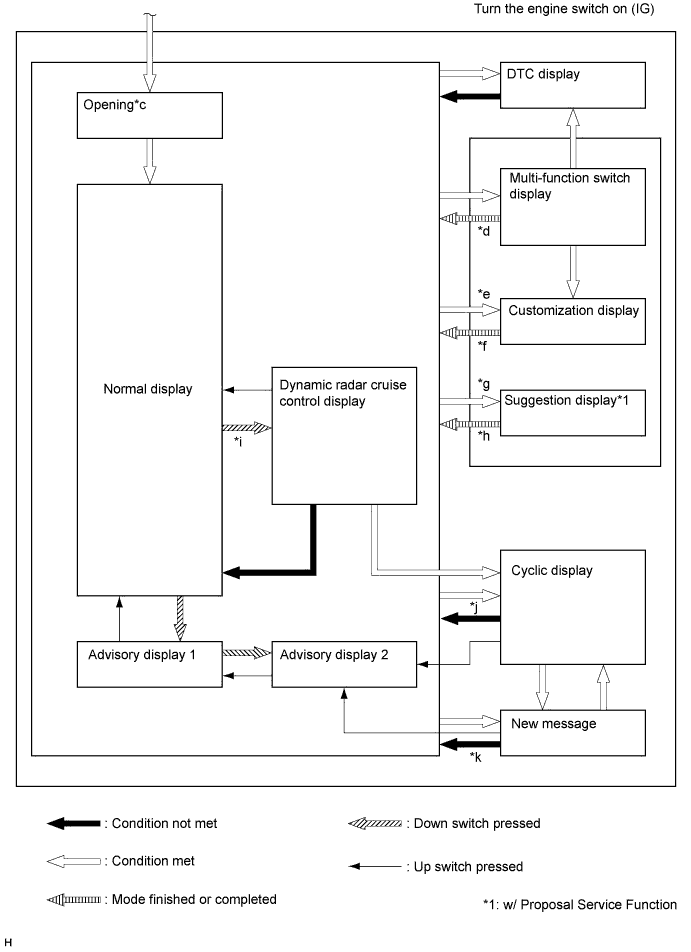
MULTI-INFORMATION DISPLAY FLOW CHART
-
Multi-information display flow chart
-
-
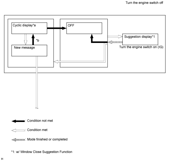
WINDOW CLOSE SUGGESTION FUNCTION
-
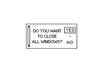
If the window close suggestion function setting is on and any window is open when the engine switch off, "DO YOU WANT TO CLOSE ALL WINDOWS?" message is displayed.
Tech Tips
-
If there is a malfunction in power window system, the proposal service function is not displayed.
-
The key-off operation can be operated during the proposal service function.
-
-
-
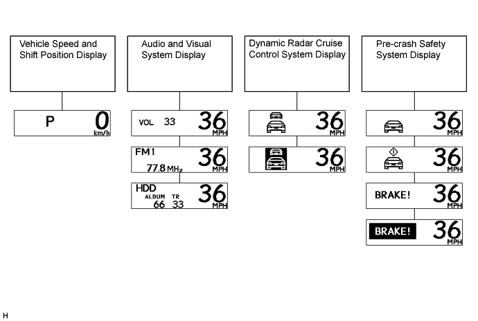
HEADUP DISPLAY
Item Detail Vehicle speed and shift position display Receives vehicle speed and shift position signals from the combination meter assembly via the direct line. Audio and visual system display Receives a navigation system signal from the multi-media module receiver assembly via the AVC-LAN. Dynamic radar cruise control system display*1 Receives an adaptive radar cruise control signal from the combination meter assembly via the direct line. Precrash brake display*1 Receives a precrash brake signal from the combination meter assembly via the direct line.
-
*1: w/ Dynamic Radar Cruise Control System
-
*2: w/ Pre-crash Safety System
-
-
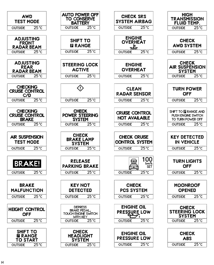
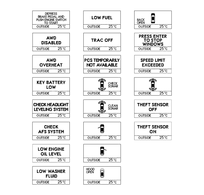
EACH WARNING DISPLAY
Tech Tips
Illustrations may differ from the actual screen displayed depending on the specifications of the vehicle.
-
for Headup display
Tech Tips
Illustrations may differ from the actual screen displayed depending on the specifications of the vehicle.
-
-
LED INITIAL CHECK
-
Check the illumination function of the warning or indicator lights listed below when turning the engine switch on (IG).
-
*1: w/ Pre-crash Safety System
-
*2: w/ AFS
-
*3: w/ Tire Pressure Warning System
-
*4: for AWD
-
*5: When the ECO mode setting is off, the meter CPU does not perform the LED initial check.
-
-