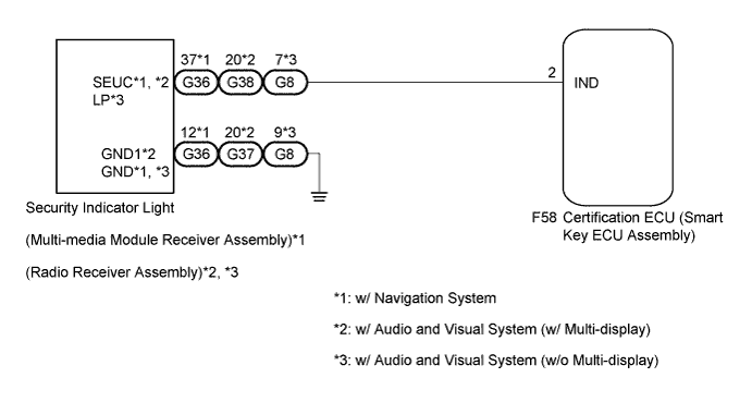
ENGINE IMMOBILISER SYSTEM Security Indicator Light Circuit
DESCRIPTION
The security indicator light blinks continuously due to a continuous signal received from the certification ECU (smart key ECU assembly) while the engine immobiliser is set.
WIRING DIAGRAM
INSPECTION PROCEDURE
Note
If the certification ECU (smart key ECU assembly) is replaced, register the key and ECU communication ID.
PROCEDURE
-
PERFORM ACTIVE TEST USING INTELLIGENT TESTER
-
Connect the intelligent tester to the DLC3.
-
Turn the engine switch on (IG).
-
Turn the intelligent tester on.
-
Enter the following menus: Body / Entry & Start / Active Test.
-
Perform the Active Test according to the display on the intelligent tester.
Entry & Start (Certification ECU (Smart Key ECU Assembly)) Tester Display Test Part Control Range Diagnostic Note Security Indicator Security indicator light ON or OFF - OK The security indicator light turns on and off according to operation via the intelligent tester.
NG 
CHECK HARNESS AND CONNECTOR (CERTIFICATION ECU - SECURITY INDICATOR LIGHT) Click here
OK 
REPLACE CERTIFICATION ECU (SMART KEY ECU ASSEMBLY)
-
-
CHECK HARNESS AND CONNECTOR (CERTIFICATION ECU - SECURITY INDICATOR LIGHT)
-
Disconnect the certification ECU (smart key ECU assembly) connector.
-
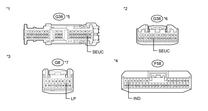
Disconnect the G36 multi-media module receiver assembly*1.
-
Disconnect the G38 radio receiver assembly*2.
-
Disconnect the G8 radio receiver assembly*3.
-
Measure the resistance according to the value(s) in the table below.
Standard Resistance Tester Connection Condition Specified Condition G36-37 (SEUC) - F58-2 (IND)*1 Always Below 1 Ω G36-37 (SEUC) - Body ground*1 Always 10 kΩ or higher G38-20 (UEUC) - F58-2 (IND)*2 Always Below 1 Ω G38-20 (UEUC) - Body ground*2 Always 10 kΩ or higher G8-7 (SEUC) - F58-2 (IND)*3 Always Below 1 Ω G8-7 (SEUC) - Body ground*3 Always 10 kΩ or higher
-
*1: w/ Navigation System
-
*2: w/ Audio and Visual System (w/ Multi-display)
-
*3: w/ Audio and Visual System (w/o Multi-display)
Text in Illustration *1 Front view of wire harness connector
(to Multi-media Module Receiver Assembly)
*2 Front view of wire harness connector
(to Radio Receiver Assembly)
*3 Front view of wire harness connector
(to Radio Receiver Assembly)
*4 Front view of wire harness connector
(to Certification ECU (Smart Key ECU Assembly))
*5 w/ Navigation System *6 w/ Audio and Visual System (w/ Multi-display) *7 w/ Audio and Visual System (w/o Multi-display) - - -
NG 
REPAIR OR REPLACE HARNESS OR CONNECTOR
OK 
-
-
CHECK HARNESS AND CONNECTOR (SECURITY INDICATOR LIGHT - BODY GROUND)
-
Measure the resistance according to the value(s) in the table below.
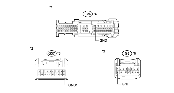
Standard Resistance Tester Connection Condition Specified Condition G36-12 (GND) - Body ground*1 Always Below 1 Ω G37-20 (GND1) - Body ground*2 Always Below 1 Ω G8-9 (GND) - Body ground*3 Always Below 1 Ω
-
*1: w/ Navigation System
-
*2: w/ Audio and Visual System (w/ Multi-display)
-
*3: w/ Audio and Visual System (w/o Multi-display)
Text in Illustration *1 Front view of wire harness connector
(to Multi-media Module Receiver Assembly)
*2 Front view of wire harness connector
(to Radio Receiver Assembly)
*3 Front view of wire harness connector
(to Radio Receiver Assembly)
*4 w/ Navigation System *5 w/ Audio and Visual System (w/ Multi-display) *6 w/ Audio and Visual System (w/o Multi-display) Result Result Proceed to OK (w/ Navigation System) A OK (w/ Audio and Visual System (w/ Multi-display)) B OK (w/ Audio and Visual System (w/o Multi-display)) C NG D -
B
REPLACE RADIO RECEIVER ASSEMBLY Click here
C
REPLACE RADIO RECEIVER ASSEMBLY Click here
D
REPAIR OR REPLACE HARNESS OR CONNECTOR
A
REPLACE MULTI-MEDIA MODULE RECEIVER ASSEMBLY Click here
-