BLOCKING SYSTEM TERMINALS OF ECU

-
CHECK TELEPHONE TRANSCEIVER ASSEMBLY

-
Disconnect the G56 telephone transceiver assembly connector.
-
Measure the resistance and voltage according to the value(s) in the table below.
Terminal No. (Symbol) Wiring Color Terminal Description Condition Specified Condition G56-6 (IG2) - G56-9 (E) R - W-B Ignition power supply Engine switch on (IG) 9 to 16 V G56-12 (+B) - G56-9 (E) W - W-B +B power supply Always 9 to 16 V G56-9 (E) - Body ground W-B - Body ground Ground Always Below 1 Ω
-
If the result is not as specified, there may be a malfunction on the wire harness side.
-
-
Reconnect the G56 telephone transceiver assembly connector.
-
Measure the voltage according to the value(s) in the table below.
Terminal No. (Symbol) Wiring Color Terminal Description Condition Specified Condition G56-1 (BLK1) - G56-9 (E) LG - W-B ID code box (immobiliser code ECU) communication input Engine switch off 11 to 14 V G56-1 (BLK1) - G56-9 (E) LG - W-B ID code box (immobiliser code ECU) communication input Within 3 seconds of engine start or within 3 seconds of engine switch turned on (IG) after battery cable disconnected and reconnected Pulse generation
(See waveform 1)
G56-2 (BLK4) - G56-9 (E) P - W-B ID code box (immobiliser code ECU) communication output Engine switch off Below 1 V G56-2 (BLK4) - G56-9 (E) P - W-B ID code box (immobiliser code ECU) communication output Within 3 seconds of engine start or within 3 seconds of engine switch turned on (IG) after battery cable disconnected and reconnected Pulse generation
(See waveform 2)
G56-7 (BLK2) - G56-9 (E) R - W-B ECM communication output Engine switch off Below 1 V G56-7 (BLK2) - G56-9 (E) R - W-B ECM communication output Within 3 seconds of engine start or within 3 seconds of engine switch turned on (IG) after battery cable disconnected and reconnected Pulse generation
(See waveform 1)
G56-8 (BLK3) - G56-9 (E) V - W-B ECM communication input Engine switch off Below 1 V G56-8 (BLK3) - G56-9 (E) V - W-B ECM communication input Within 3 seconds of engine start or within 3 seconds of engine switch turned on (IG) after battery cable disconnected and reconnected Pulse generation
(See waveform 2)
-
If the result is not as specified, the telephone transceiver assembly may have a malfunction.
-
-
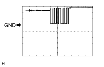
Inspect using an oscilloscope.
Note
The waveform shown in the illustration is an example for reference only. Noise, chattering, etc. are not shown.
-
Waveform 1 (Reference)
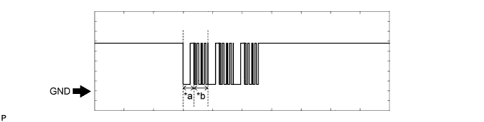
Text in Illustration *a Approximately 160 ms *b Approximately 270 ms Measurement Condition Item Content Tester Connection
-
G56-1 (BLK1) - G56-9 (E)
-
G56-7 (BLK2) - G56-9 (E)
Tool Setting 2 V/DIV., 500 ms./DIV. Condition Within 3 seconds of engine start or within 3 seconds of engine switch turned on (IG) after battery cable disconnected and reconnected -
-
Waveform 2 (Reference)
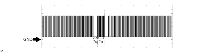
Text in Illustration *a Approximately 160 ms *b Approximately 270 ms Measurement Condition Item Content Tester Connection
-
G56-2 (BLK4) - G56-9 (E)
-
G56-8 (BLK3) - G56-9 (E)
Tool Setting 2 V/DIV., 500 ms./DIV. Condition Within 3 seconds of engine start or within 3 seconds of engine switch turned on (IG) after battery cable disconnected and reconnected -
-
-
-
CHECK ID CODE BOX (IMMOBILISER CODE ECU)
-
Disconnect the F45 ID code box (immobiliser code ECU) connector.

-
Measure the resistance and voltage according to the value(s) in the table below.
Tester Connection (Symbol) Wiring Color Terminal Description Condition Specified Condition F45-1 (+B) - F45-8 (GND) B - W-B +B power supply Always 11 to 14 V F45-8 (GND) - Body ground W-B - Body ground Ground Always Below 1 Ω
-
If the result is not as specified, there may be a malfunction in the wire harness.
-
-
Reconnect the F45 ID code box (immobiliser code ECU) connector.
-
Measure the voltage according to the value(s) in the table below.
Tester Connection (Symbol) Wiring Color Terminal Description Condition Specified Condition F45-5 (EFII) - F45-8 (GND) LG - W-B ECM input signal Engine switch off 11 to 14 V F45-5 (EFII) - F45-8 (GND) LG - W-B ECM input signal Within 3 seconds after starter operates and initial combustion occurs, or within 3 seconds after engine switch first turned on (IG) after battery disconnected and connected Pulse generation
(See waveform 1)
F45-6 (EFIO) - F45-8 (GND) P - W-B ECM output signal Engine switch off Below 1 V F45-6 (EFIO) - F45-8 (GND) P - W-B ECM output signal Engine switch on (IG) Pulse generation
(See waveform 2)
-
If the result is not as specified, the ID code box (immobiliser code ECU) may have a malfunction.
-
-
Inspect using an oscilloscope.
-
Waveform 1 (Reference)
Text in Illustration *a Approximately 160 ms *b Approximately 270 ms Item Content Tester Connection F45-5 (EFII) - F45-8 (GND) Tool Setting 5 V/DIV., 500 ms./DIV. Condition Within 3 seconds after starter operates and initial combustion occurs, or within 3 seconds after engine switch first turned on (IG) after battery disconnected and connected -
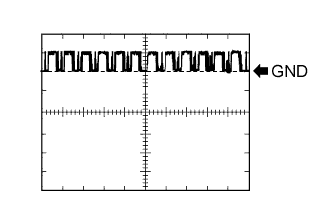
Waveform 2 (Reference)
Text in Illustration *a Approximately 160 ms *b Approximately 270 ms Item Content Tester Connection F45-6 (EFIO) - F45-8 (GND) Tool Setting 10 V/DIV., 100 ms./DIV. Condition Engine switch on (IG)
-
-
-
CHECK ECM
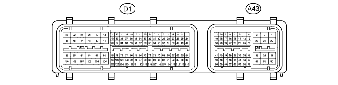
Tech Tips
The standard voltage between each pair of ECM terminals is shown in the table below. The appropriate conditions for checking each pair of terminals are also indicated. The result of checks should be compared with the standard voltage or resistance for that pair of terminals, displayed in the "Specified Condition" column. The illustration above can be used as a reference to identify the ECM terminal locations.
Tester Connection (Symbol) Wiring Color Terminal Description Condition Specified Condition A43-3 (+B) - D1-81 (E1) BR - BR Power source of ECM Engine switch on (IG) 11 to 14 V A43-2 (+B2) - D1-81 (E1) L - BR Power source of ECM Engine switch on (IG) 11 to 14 V A43-1 (BATT) - D1-81 (E1) LG - BR Battery (for measuring the battery voltage and for the ECM memory) Always 11 to 14 V D1-81 (E1) - Body ground BR - Body ground Ground Always Below 1 Ω A43-29 (IMO) - D1-81 (E1) R - BR ID code box (immobiliser code ECU) output signal Engine switch off 11 to 14 V A43-29 (IMO) - D1-81 (E1) R - BR ID code box (immobiliser code ECU) output signal Within 3 seconds after starter operates and initial combustion occurs, or within 3 seconds after engine switch first turned on (IG) after battery disconnected and connected Pulse generation
(See waveform 1)
A43-40 (IMI) - D1-81 (E1) P - BR ID code box (immobiliser code ECU) input signal Engine switch off Below 1 V A43-40 (IMI) - D1-81 (E1) P - BR ID code box (immobiliser code ECU) input signal Engine switch on (IG) Pulse generation
(See waveform 2)
-
Waveform:
-
Waveform 1 (Reference)
Item Content Tester Connection A43-29 (IMO) - D1-81 (E1) Tool Setting 5 V/DIV., 500 ms./DIV. Condition Within 3 seconds after starter operates and initial combustion occurs, or within 3 seconds after engine switch first turned on (IG) after battery disconnected and connected -
Waveform 2 (Reference)
Item Content Tester Connection A43-40 (IMI) - D1-81 (E1) Tool Setting 5 V/DIV., 100 ms./DIV. Condition Engine switch on (IG)
-
-