ENTRY AND START SYSTEM (for Start Function) Power Source Mode does not Change to ON (IG)
DESCRIPTION
When the engine switch is pushed with the electrical key in the cabin, the power management control ECU receives signals to change the power source mode.
Tech Tips
To allow use of the intelligent tester to inspect the push-button start function when the power source mode is off, repeat opening and closing any of the doors. Opening and closing a door establishes communication between the intelligent tester and the power management control ECU. (Opening and closing a door can also be simulated by operating a door courtesy light switch.)
WIRING DIAGRAM
Refer to DTC B2271 Click here.
INSPECTION PROCEDURE
PROCEDURE
-
CHECK HARNESS AND CONNECTOR (BATTERY - POWER MANAGEMENT CONTROL ECU)
-
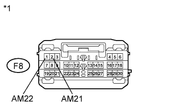
Text in Illustration *1 Front view of wire harness connector
(to Power Management Control ECU)
Disconnect the F8 connector from the power management control ECU.
-
Measure the voltage according to the value(s) in the table below.
Standard Voltage Tester Connection Condition Specified Condition F8-1 (AM22) - Body ground Always 9.5 to 16 V F8-2 (AM21) - Body ground Always 9.5 to 16 V
NG 
REPAIR OR REPLACE HARNESS OR CONNECTOR (BATTERY - POWER MANAGEMENT CONTROL ECU)
OK 
-
-
CHECK HARNESS AND CONNECTOR (POWER MANAGEMENT CONTROL ECU - BODY GROUND)
-
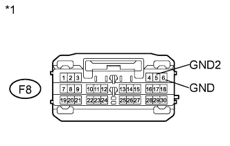
Text in Illustration *1 Front view of wire harness connector
(to Power Management Control ECU)
Disconnect the F8 connector from the power management control ECU.
-
Measure the resistance according to the value(s) in the table below.
Standard Resistance Tester Connection Condition Specified Condition F8-5 (GND2) - Body ground Always Below 1 Ω F8-6 (GND) - Body ground Always Below 1 Ω
NG
REPAIR OR REPLACE HARNESS OR CONNECTOR (POWER MANAGEMENT CONTROL ECU - BODY GROUND)
OK
-
-
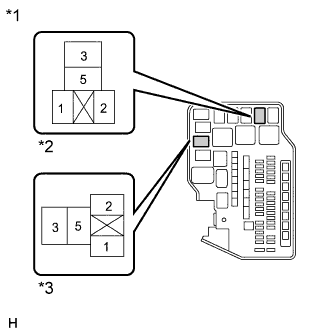
INSPECT IG1 RELAY
-
Remove the IG1 relay from the engine room relay block assembly.
-
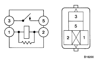
Measure the resistance according to the value(s) in the table below.
Standard Resistance Tester Connection Condition Specified Condition 1 - 2 Always 130 to 230 Ω 3 - 5 When battery voltage is not applied to terminals 1 and 2 10 kΩ or higher 3 - 5 When battery voltage is applied to terminals 1 and 2 Below 1 Ω
NG
REPLACE IG1 RELAY
OK
-
-
INSPECT IG2 RELAY
-
Remove the IG2 relay from the engine room relay block assembly.
-
Measure the resistance according to the value(s) in the table below.
Standard Resistance Tester Connection Condition Specified Condition 1 - 2 Always 130 to 230 Ω 3 - 5 When battery voltage is not applied to terminals 1 and 2 10 kΩ or higher 3 - 5 When battery voltage is applied to terminals 1 and 2 Below 1 Ω
NG
REPLACE IG2 RELAY
OK
-
-
INSPECT INSTRUMENT PANEL JUNCTION BLOCK ASSEMBLY (IN NO. 1, IG NO. 2, AND IG NO. 3 RELAY)
-
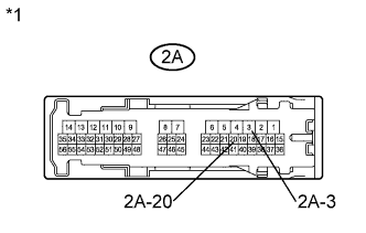
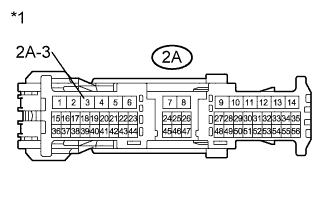
Text in Illustration *1 Component without harness connected
(Instrument Panel Junction Block Assembly)
Remove the instrument panel junction block assembly Click here.
-
Measure the resistance according to the value(s) in the table below.
Standard Resistance Tester Connection Condition Specified Condition 2A-20 - 2A-3 20°C (68°F) 54.32 to 79.32 Ω
NG
REPLACE INSTRUMENT PANEL JUNCTION BLOCK ASSEMBLY Click here
OK
-
-
CHECK HARNESS AND CONNECTOR
-
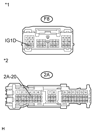
Text in Illustration *1 Front view of wire harness connector
(to Power Management Control ECU)
*2 Front view of wire harness connector
(to Instrument Panel Junction Block Assembly)
Measure the resistance according to the value(s) in the table below.
Standard Resistance Tester Connection Condition Specified Condition F8-20 (IG1D) - 2A-20 Always Below 1 Ω F8-20 (IG1D) - Body ground Always 10 kΩ or higher
NG
REPAIR OR REPLACE HARNESS OR CONNECTOR
OK
-
-
CHECK HARNESS AND CONNECTOR (INSTRUMENT PANEL JUNCTION BLOCK ASSEMBLY - BODY GROUND)
-
Text in Illustration *1 Front view of wire harness connector
(to Instrument Panel Junction Block Assembly)
Measure the resistance according to the value(s) in the table below.
Standard Resistance Tester Connection Condition Specified Condition 2A-3 - Body ground Always Below 1 Ω
NG
REPAIR OR REPLACE HARNESS OR CONNECTOR (INSTRUMENT PANEL JUNCTION BLOCK ASSEMBLY - BODY GROUND)
OK
-
-
CHECK HARNESS AND CONNECTOR (INSTRUMENT PANEL JUNCTION BLOCK ASSEMBLY - IG1 RELAY)
-
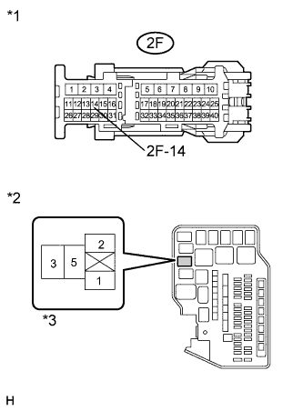
Text in Illustration *1 Front view of wire harness connector
(to Instrument Panel Junction Block Assembly)
*2 Component without relay connected
(Engine Room Relay Block Assembly)
*3 IG1 Relay Terminal Measure the resistance according to the value(s) in the table below.
Standard Resistance Tester Connection Condition Specified Condition 2F-14 - Engine room relay block IG1 relay terminal 2 Always Below 1 Ω 2F-14 - Body ground Always 10 kΩ or higher
NG
REPAIR OR REPLACE HARNESS OR CONNECTOR (INSTRUMENT PANEL JUNCTION BLOCK ASSEMBLY - IG1 RELAY)
OK
-
-
CHECK HARNESS AND CONNECTOR (POWER MANAGEMENT CONTROL ECU - IG2 RELAY)
-
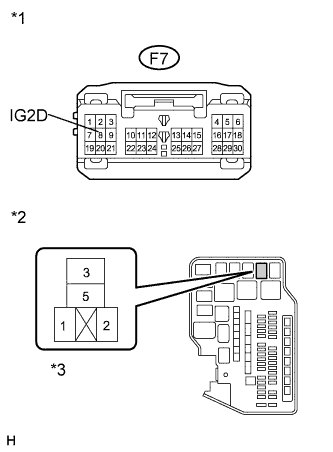
Text in Illustration *1 Front view of wire harness connector
(to Power Management Control ECU)
*2 Component without relay connected
(Engine Room Relay Block Assembly)
*3 IG2 Relay Terminal Disconnect the F7 connector.
-
Measure the resistance according to the value(s) in the table below.
Standard Resistance Tester Connection Condition Specified Condition F7-8 (IG2D) - Engine room relay block IG2 relay terminal 2 Always Below 1 Ω F7-8 (IG2D) - Body ground Always 10 kΩ or higher
NG
REPAIR OR REPLACE HARNESS OR CONNECTOR (POWER MANAGEMENT CONTROL ECU - IG2 RELAY)
OK
-
-
CHECK HARNESS AND CONNECTOR (ENGINE ROOM RELAY BLOCK ASSEMBLY - BODY GROUND)
-
Text in Illustration *1 Component without harness connected
(Engine Room Relay Block Assembly)
*2 IG2 Relay Terminal *3 IG1 Relay Terminal Measure the resistance according to the value(s) in the table below.
Standard Resistance Tester Connection Condition Specified Condition Engine room relay block IG1 relay terminal 1 - Body ground Always Below 1 Ω Engine room relay block IG2 relay terminal 1 - Body ground Always Below 1 Ω
NG
REPAIR OR REPLACE HARNESS OR CONNECTOR (ENGINE ROOM RELAY BLOCK ASSEMBLY - BODY GROUND)
OK
-
-
CHECK POWER MANAGEMENT CONTROL ECU
-
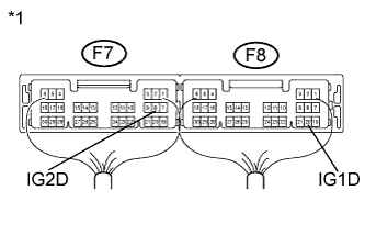
Text in Illustration *1 Component with harness connected
(Power Management Control ECU)
Install the instrument panel junction block assembly Click here.
-
Reconnect the F7 and F8 connectors.
-
Measure the voltage according to the value(s) in the table below.
Standard Voltage Tester Connection Condition Specified Condition F7-8 (IG2D) - Body ground Engine switch on (IG) Output voltage at terminal AM21 or AM22 -2.5 V or more F8-20 (IG1D) - Body ground Engine switch on (IG) Output voltage at terminal AM21 or AM22 -2.5 V or more -
Proceed to the next step based on the inspection result.
Result Result Proceed to OK A NG (for LHD) B NG (for RHD) C
B
REPLACE POWER MANAGEMENT CONTROL ECU (for LHD) Click here
C
REPLACE POWER MANAGEMENT CONTROL ECU (for RHD) Click here
A 
USE SIMULATION METHOD TO CHECK Click here
-