CAN COMMUNICATION SYSTEM, Diagnostic DTC:U1002

| DTC Code | DTC Name |
|---|---|
| U1002 | Lost Communication with Gateway Module (Power Management1) |
DESCRIPTION
-
The power management control ECU will store this DTC when no signals can be received from the ECUs that have been memorized as those that are connected to the CAN No. 2 bus.
-
When the power management control ECU receives a response signal from the ECUs connected to the CAN No. 2 bus, the power management control ECU recognizes and memorizes that the ECU is connected to the CAN No. 2 bus. Based on this memorized data, the power management control ECU monitors for malfunctions in the ECUs connected to the CAN No. 2 bus when communicating with those ECUs. If the power management control ECU cannot receive response signals from the ECUs that have been memorized as those connected to the CAN No. 2 bus, the power management control ECU determines that a malfunction exists.
| DTC No. | DTC Detection Condition | Trouble Area |
|---|---|---|
| U1002 | Power management control ECU cannot receive signals from all ECUs that have been memorized as those connected to the CAN No. 2 bus. |
|
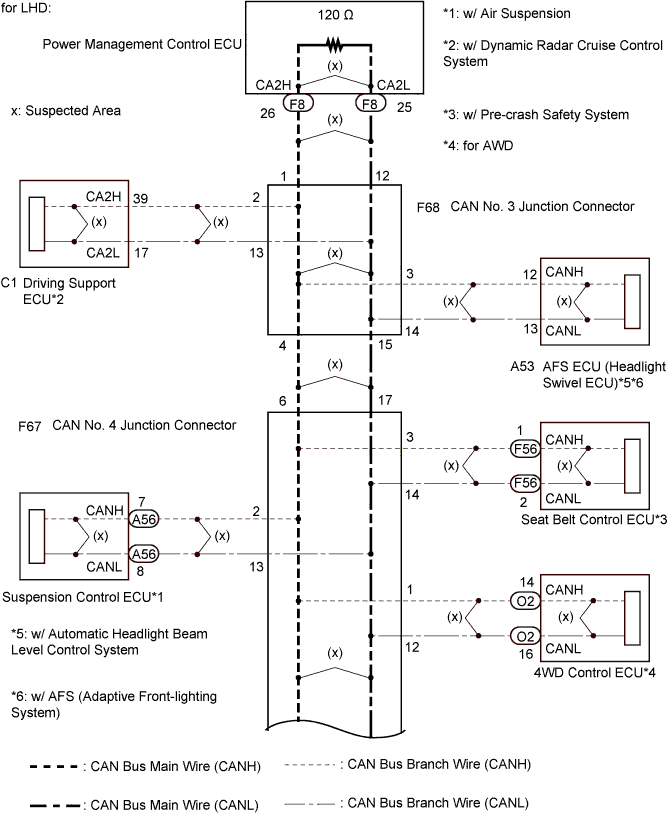
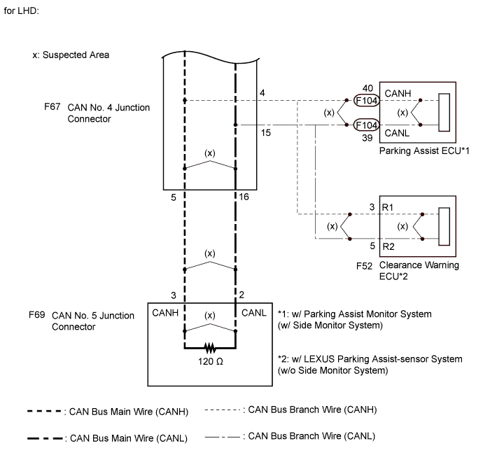
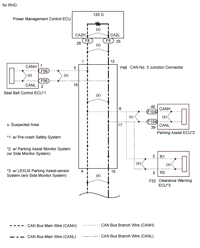
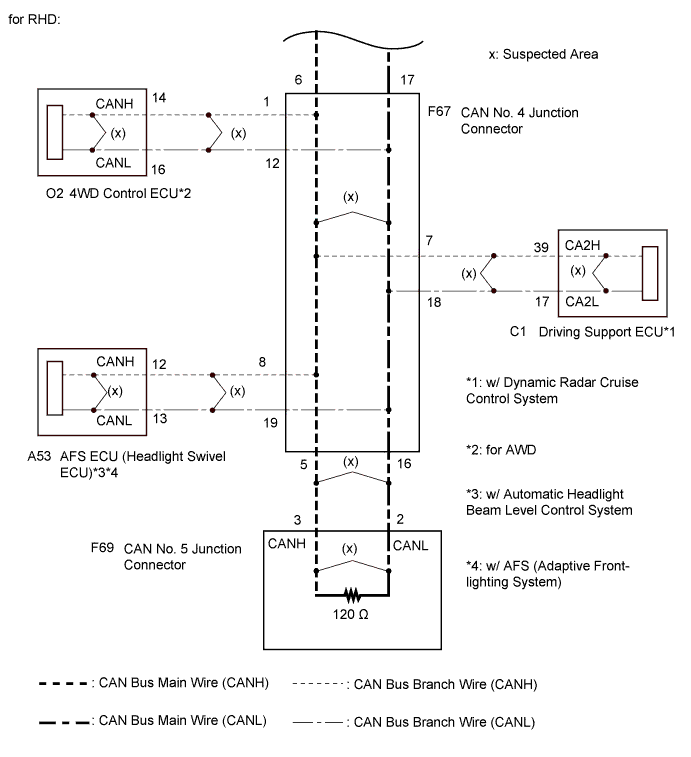
WIRING DIAGRAM
INSPECTION PROCEDURE
Note
-
Turn the engine switch off before measuring the resistances between CAN bus main wires and between CAN bus branch wires.
-
Turn the engine switch off before inspecting CAN bus wires for a ground short.
-
After the engine switch is turned off, check that the key reminder warning system and light reminder warning system are not operating.
-
Before measuring the resistance, leave the vehicle as is for at least 1 minute and do not operate the engine switch, any other switches or the doors. If any doors need to be opened in order to check connectors, open the doors and leave them open.
Tech Tips
-
Operating the engine switch, any other switches or a door triggers related ECU and sensor communication on the CAN. This communication will cause the resistance value to change.
-
Even after DTCs are cleared, if a DTC is stored again after driving the vehicle for a while, the malfunction may be occurring due to vibration of the vehicle. In such a case, wiggling the ECUs or wire harness while performing the inspection below may help determine the cause of the malfunction.
PROCEDURE
-
CHECK CAN NO. 2 BUS WIRE
-
Turn the engine switch off.
-
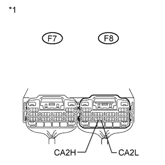
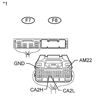
Text in Illustration *1 Component with harness connected
(Power Management Control ECU)
Measure the resistance according to the value(s) in the table below.
Standard Resistance Tester Connection Switch Condition Specified Condition Result F8-26 (CA2H) - F8-25 (CA2L) Engine switch off 54 to 69 Ω Below 54 Ω:
Short circuit between bus lines
70 Ω or higher:
Open circuit in a main bus line
Result Result Proceed to OK A Open circuit in CAN main bus line B Short circuit between bus lines (LHD) C Short circuit between bus lines (RHD) D
B 
CHECK FOR OPEN IN CAN NO. 2 BUS MAIN WIRE (POWER MANAGEMENT CONTROL ECU MAIN WIRE) Click here
C
CHECK FOR SHORT IN CAN NO. 2 BUS WIRE (POWER MANAGEMENT CONTROL ECU) Click here
D
CHECK FOR SHORT IN CAN NO. 2 BUS WIRE (POWER MANAGEMENT CONTROL ECU) Click here
A 
-
-
CHECK CAN NO. 2 BUS WIRE
-
Turn the engine switch off.
-
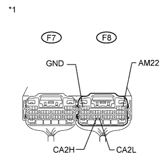
Text in Illustration *1 Component with harness connected
(Power Management Control ECU)
Measure the resistance according to the value(s) in the table below.
Standard Resistance Tester Connection Switch Condition Specified Condition Result F8-26 (CA2H) - F8-6 (GND) Engine switch off 200 Ω or higher Below 200 Ω:
CANH ground short
F8-25 (CA2L) - F8-6 (GND) Engine switch off 200 Ω or higher Below 200 Ω:
CANL ground short
-
Disconnected the cable from the negative (-) battery terminal.
-
Measure the resistance according to the value(s) in the table below.
Standard Resistance Tester Connection Condition Specified Condition Result F8-26 (CA2H) - F8-1 (AM22) Cable disconnected from negative (-) battery terminal 6 kΩ or higher Below 6 kΩ:
CANH +B short
F8-25 (CA2L) - F8-1 (AM22) Cable disconnected from negative (-) battery terminal 6 kΩ or higher Below 6 kΩ:
CANL +B short
Result Result Proceed to OK A
-
Ground short
-
+B short
(for LHD)
B
-
Ground short
-
+B short
(for RHD)
C -
B
CHECK FOR SHORT IN CAN NO. 2 BUS WIRE (POWER MANAGEMENT CONTROL ECU) Click here
C
CHECK FOR SHORT IN CAN NO. 2 BUS WIRE (POWER MANAGEMENT CONTROL ECU) Click here
A 
REPLACE POWER MANAGEMENT CONTROL ECU
-
-
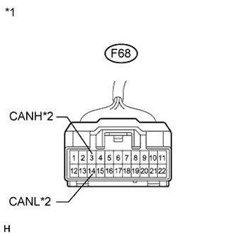
CHECK FOR OPEN IN CAN NO. 2 BUS MAIN WIRE (POWER MANAGEMENT CONTROL ECU MAIN WIRE)
-
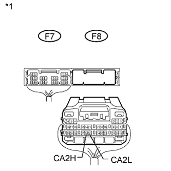
Text in Illustration *1 Rear view of wire harness connector
(to Power Management Control ECU)
Disconnect the power management control ECU connector.
-
Measure the resistance according to the value(s) in the table below.
Standard Resistance Tester Connection Switch Condition Specified Condition F8-26 (CA2H) - F8-25 (CA2L) Engine switch off 108 to 132 Ω
NG
CHECK FOR OPEN IN CAN NO. 2 BUS MAIN WIRE (CAN NO. 3 J/C) Click here
OK
REPLACE POWER MANAGEMENT CONTROL ECU
-
-
CHECK FOR OPEN IN CAN NO. 2 BUS MAIN WIRE (CAN NO. 3 J/C)
-
Reconnect the power management control ECU connector.
-
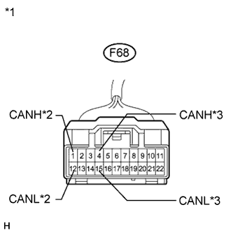
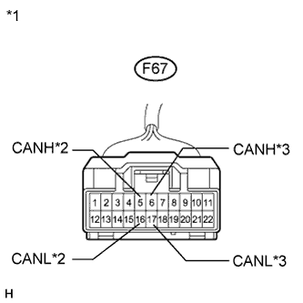
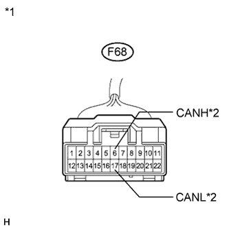
Text in Illustration *1 Front view of wire harness connector
(to CAN No. 3 Junction Connector)
*2 to Power Management Control ECU *3 to CAN No. 4 Junction Connector Disconnect the CAN No. 3 junction connector.
-
Measure the resistance according to the value(s) in the table below.
Standard Resistance Tester Connection Switch Condition Specified Condition Connected to F68-1 (CANH) - F68-12 (CANL) Engine switch off 108 to 132 Ω Power management control ECU F68-4 (CANH) - F68-15 (CANL) Engine switch off 108 to 132 Ω CAN No. 4 junction connector Result Result Proceed to OK A NG (to Power management control ECU main wire) B NG (to CAN No. 4 junction connector main wire) C
B 
REPAIR OR REPLACE CAN BUS MAIN WIRE OR CONNECTOR (CAN NO. 3 J/C - POWER MANAGEMENT CONTROL ECU)
C
CHECK FOR OPEN IN CAN NO. 2 BUS MAIN WIRE (CAN NO. 4 J/C) Click here
A
REPLACE CAN NO. 3 JUNCTION CONNECTOR
-
-
CHECK FOR OPEN IN CAN NO. 2 BUS MAIN WIRE (CAN NO. 4 J/C)
-
Reconnect the CAN No. 3 junction connector.
-
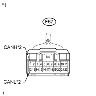
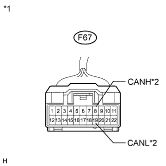
Text in Illustration *1 Front view of wire harness connector
(to CAN No. 4 Junction Connector)
*2 to CAN No. 5 Junction Connector *3 to CAN No. 3 Junction Connector Disconnect the CAN No. 4 junction connector.
-
Measure the resistance according to the value(s) in the table below.
Standard Resistance Tester Connection Switch Condition Specified Condition Connected to F67-5 (CANH) - F67-16 (CANL) Engine switch off 108 to 132 Ω CAN No. 5 junction connector F67-6 (CANH) - F67-17 (CANL) Engine switch off 108 to 132 Ω CAN No. 3 junction connector Result Result Proceed to OK A NG (to CAN No. 3 junction connector main wire) B NG (to CAN No. 5 junction connector main wire) C
B
REPAIR OR REPLACE CAN BUS MAIN WIRE OR CONNECTOR (CAN NO. 3 J/C - CAN NO. 4 J/C)
C
CHECK FOR OPEN IN CAN NO. 2 BUS MAIN WIRE (CAN NO. 5 J/C) Click here
A
REPLACE CAN NO. 4 JUNCTION CONNECTOR
-
-
CHECK FOR OPEN IN CAN NO. 2 BUS MAIN WIRE (CAN NO. 5 J/C)
-
Reconnect the CAN No. 4 junction connector.
-
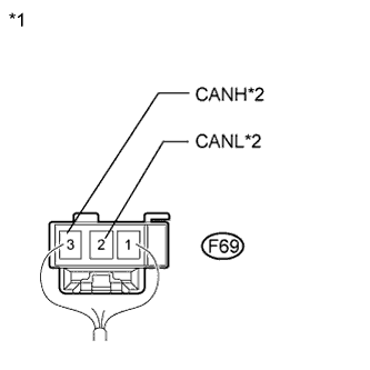
Text in Illustration *1 Rear view of wire harness connector
(to CAN No. 5 Junction Connector)
*2 to CAN No. 4 Junction Connector Disconnect the CAN No. 5 junction connector.
-
Measure the resistance according to the value(s) in the table below.
Standard Resistance Tester Connection Switch Condition Specified Condition Connected to F69-3 (CANH) - F69-2 (CANL) Engine switch off 108 to 132 Ω CAN No. 4 junction connector
NG
REPAIR OR REPLACE CAN BUS MAIN WIRE OR CONNECTOR (CAN NO. 4 J/C - CAN NO. 5 J/C)
OK
REPLACE CAN NO. 5 JUNCTION CONNECTOR
-
-
CHECK FOR SHORT IN CAN NO. 2 BUS WIRE (POWER MANAGEMENT CONTROL ECU)
-
Text in Illustration *1 Rear view of wire harness connector
(to Power Management Control ECU)
Disconnect the power management control ECU connector.
-
Measure the resistance according to the value(s) in the table below.
Standard Resistance Tester Connection Switch Condition Specified Condition F8-26 (CA2H) - F8-25 (CA2L) Engine switch off 108 to 132 Ω
NG
CHECK FOR SHORT IN CAN NO. 2 BUS WIRE (CAN NO. 3 J/C) Click here
OK
REPLACE POWER MANAGEMENT CONTROL ECU
-
-
CHECK FOR SHORT IN CAN NO. 2 BUS WIRE (CAN NO. 3 J/C)
-
Reconnect the power management control ECU connector.
-
Text in Illustration *1 Front view of wire harness connector
(to CAN No. 3 Junction Connector)
*2 to Power Management Control ECU *3 to CAN No. 4 Junction Connector Disconnect the CAN No. 3 junction connector.
-
Measure the resistance according to the value(s) in the table below.
Standard Resistance Tester Connection Switch Condition Specified Condition Connected to F68-1 (CANH) - F68-12 (CANL) Engine switch off 108 to 132 Ω Power management control ECU F68-4 (CANH) - F68-15 (CANL) Engine switch off 108 to 132 Ω CAN No. 4 junction connector Result Result Proceed to OK A NG (to Power management control ECU main wire) B NG (to CAN No. 4 junction connector main wire) C
B
REPAIR OR REPLACE CAN BUS MAIN WIRE OR CONNECTOR (CAN NO. 3 J/C - POWER MANAGEMENT CONTROL ECU)
C
CHECK FOR SHORT IN CAN NO. 2 BUS WIRE (CAN NO. 4 J/C) Click here
A
-
-
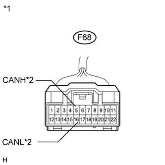
CHECK FOR SHORT IN CAN NO. 2 BUS WIRE (CAN NO. 3 J/C - AFS ECU)
-
Disconnect the AFS ECU connector.
-
Text in Illustration *1 Front view of wire harness connector
(to CAN No. 3 Junction Connector)
*2 to AFS ECU Measure the resistance according to the value(s) in the table below.
Standard Resistance Tester Connection Switch Condition Specified Condition F68-3 (CANH) - F68-14 (CANL) Engine switch off 1 MΩ or higher
NG
REPAIR OR REPLACE CAN NO. 2 BUS BRANCH WIRE OR CONNECTOR (CAN NO. 3 J/C - AFS ECU)
OK
-
-
CHECK FOR SHORT IN CAN NO. 2 BUS WIRE (CAN NO. 3 J/C - DRIVING SUPPORT ECU)
-
Disconnect the driving support ECU connector.
-

Text in Illustration *1 Front view of wire harness connector
(to CAN No. 3 Junction Connector)
*2 to Driving Support ECU Measure the resistance according to the value(s) in the table below.
Standard Resistance Tester Connection Switch Condition Specified Condition F68-2 (CANH) - F68-13 (CANL) Engine switch off 1 MΩ or higher
NG
REPAIR OR REPLACE CAN NO. 2 BUS BRANCH WIRE OR CONNECTOR (CAN NO. 3 J/C - DRIVING SUPPORT ECU)
OK
-
-
CHECK FOR SHORT IN CAN NO. 2 BUS WIRE (CAN NO. 3 J/C)
-
Reconnect the CAN No. 3 junction connector.
-
Text in Illustration *1 Component with harness connected
(Power Management Control ECU)
Measure the resistance according to the value(s) in the table below.
Note
The resistance must be measured after the main wire connected ECU and junction connector are reconnected.
Standard Resistance Tester Connection Switch Condition Result F8-26 (CA2H) - F8-25 (CA2L) Engine switch off 54 to 69 Ω
NG
REPLACE CAN NO. 3 JUNCTION CONNECTOR
OK
-
-
CHECK FOR SHORT IN CAN NO. 2 BUS WIRE (ECUS)
-
Text in Illustration *1 Component with harness connected
(Power Management Control ECU)
Connect the probes of an ohmmeter to terminals 26 (CA2H) and 25 (CA2L) of the power management control ECU.
-
While observing the resistance value shown on the tester, reconnect each ECU connector until the resistance becomes abnormal (below 54 Ω).
-
Replace the ECU that caused the total resistance to drop below 54 Ω when it was reconnected.
Tech Tips
If the resistance becomes abnormal when an ECU connector is reconnected, there may be a short in the ECU.
NEXT
REPLACE ECU
-
-
CHECK FOR SHORT IN CAN NO. 2 BUS WIRE (CAN NO. 4 J/C)
-
Reconnect the CAN No. 3 junction connector.
-
Text in Illustration *1 Front view of wire harness connector
(to CAN No. 4 Junction Connector)
*2 to CAN No. 5 Junction Connector *3 to CAN No. 3 Junction Connector Disconnect the CAN No. 4 junction connector.
-
Measure the resistance according to the value(s) in the table below.
Standard Resistance Tester Connection Switch Condition Specified Condition Connected to F67-5 (CANH) - F67-16 (CANL) Engine switch off 108 to 132 Ω CAN No. 5 junction connector F67-6 (CANH) - F67-17 (CANL) Engine switch off 108 to 132 Ω CAN No. 3 junction connector Result Result Proceed to OK A NG (to CAN No. 3 junction connector main wire) B NG (to CAN No. 5 junction connector main wire) C
B
REPAIR OR REPLACE CAN BUS MAIN WIRE OR CONNECTOR (CAN NO. 3 J/C - CAN NO. 4 J/C)
C
CHECK FOR SHORT IN CAN NO. 2 BUS WIRE (CAN NO. 5 J/C) Click here
A
-
-
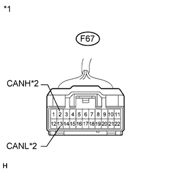
CHECK FOR SHORT IN CAN NO. 2 BUS WIRE (CAN NO. 4 J/C - 4WD CONTROL ECU)
Tech Tips
For 2WD vehicles, go to the next step.
-
Disconnect the 4WD control ECU connector.
-
Text in Illustration *1 Front view of wire harness connector
(to CAN No. 4 Junction Connector)
*2 to 4WD Control ECU Measure the resistance according to the value(s) in the table below.
Standard Resistance Tester Connection Switch Condition Specified Condition F67-1 (CANH) - F67-12 (CANL) Engine switch off 1 MΩ or higher
NG
REPAIR OR REPLACE CAN NO. 2 BUS BRANCH WIRE OR CONNECTOR (CAN NO. 4 J/C - 4WD CONTROL ECU)
OK
-
-
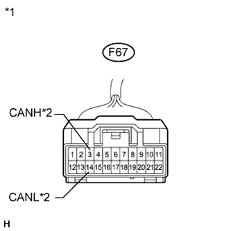
CHEKC FOR SHORT IN CAN NO. 2 BUS WIRE (CAN NO. 4 J/C - SUSPENSION CONTROL ECU)
Tech Tips
For vehicles without air suspension, go to the next step.
-
Disconnect the suspension control ECU connector.
-
Text in Illustration *1 Front view of wire harness connector
(to CAN No. 4 Junction Connector)
*2 to Suspension Control ECU Measure the resistance according to the value(s) in the table below.
Standard Resistance Tester Connection Switch Condition Specified Condition F67-2 (CANH) - F67-13 (CANL) Engine switch off 1 MΩ or higher
NG
REPAIR OR REPLACE CAN NO. 2 BUS BRANCH WIRE OR CONNECTOR (CAN NO. 4 J/C - SUSPENSION CONTROL ECU)
OK
-
-
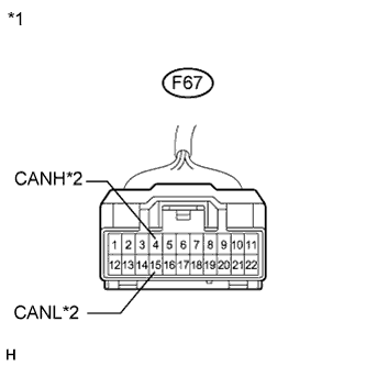
CHECK FOR SHORT IN CAN NO. 2 BUS WIRE (CAN NO. 4 J/C - SEAT BELT CONTROL ECU)
Tech Tips
For vehicles without pre-crash safety system, go to the next step.
-
Disconnect the seat belt control ECU connector.
-
Text in Illustration *1 Front view of wire harness connector
(to CAN No. 4 Junction Connector)
*2 to Seat Belt Control ECU Measure the resistance according to the value(s) in the table below.
Standard Resistance Tester Connection Switch Condition Specified Condition F67-3 (CANH) - F67-14 (CANL) Engine switch off 1 MΩ or higher
NG
REPAIR OR REPLACE CAN NO. 2 BUS BRANCH WIRE OR CONNECTOR (CAN NO. 4 J/C - SEAT BELT CONTROL ECU)
OK
-
-
CHECK FOR SHORT IN CAN NO. 2 BUS WIRE (CAN NO. 4 J/C - PARKING ASSIST ECU)
Tech Tips
For vehicles without parking assist monitor system (w/ side monitor system), go to the next step.
-
Disconnect the parking assist ECU connector.
-
Text in Illustration *1 Front view of wire harness connector
(to CAN No. 4 Junction Connector)
*2 to Parking Assist ECU Measure the resistance according to the value(s) in the table below.
Standard Resistance Tester Connection Switch Condition Specified Condition F67-4 (CANH) - F67-15 (CANL) Engine switch off 1 MΩ or higher
NG
REPAIR OR REPLACE CAN NO. 2 BUS BRANCH WIRE OR CONNECTOR (CAN NO. 4 J/C - PARKING ASSIST ECU)
OK
-
-
CHECK FOR SHORT IN CAN NO. 2 BUS WIRE (CAN NO. 4 J/C - CLEARANCE WARNING ECU)
Tech Tips
For vehicles without LEXUS parking assist-sensor system (w/o side monitor system), go to the next step.
-
Disconnect the clearance warning ECU connector.
-
Text in Illustration *1 Front view of wire harness connector
(to CAN No. 4 Junction Connector)
*2 to Clearance Warning ECU Measure the resistance according to the value(s) in the table below.
Standard Resistance Tester Connection Switch Condition Specified Condition F67-4 (CANH) - F67-15 (CANL) Engine switch off 1 MΩ or higher
NG
REPAIR OR REPLACE CAN NO. 2 BUS BRANCH WIRE OR CONNECTOR (CAN NO. 4 J/C - CLEARANCE WARNING ECU)
OK
-
-
CHECK FOR SHORT IN CAN NO. 2 BUS WIRE (CAN NO. 4 J/C)
-
Reconnect the CAN No. 4 junction connector.
-
Text in Illustration *1 Component with harness connector
(Power Management Control ECU)
Measure the resistance according to the value(s) in the table below.
Standard Resistance Tester Connection Switch Condition Result F8-26 (CA2H) - F8-25 (CA2L) Engine switch off 54 to 69 Ω Note
The resistance must be measured after the main wire connected ECU and junction connector are reconnected.
NG
REPLACE CAN NO. 4 JUNCTION CONNECTOR
OK
-
-
CHECK FOR SHORT IN CAN NO. 2 BUS WIRE (ECUS)
-
Text in Illustration *1 Component with harness connector
(Power Management Control ECU)
Connect the probes of an ohmmeter to terminals 26 (CA2H) and 25 (CA2L) of the power management control ECU.
-
While observing the resistance value shown on the tester, reconnect each ECU connector until the resistance becomes abnormal (below 54 Ω).
-
Replace the ECU that caused the total resistance to drop below 54 Ω when it was reconnected.
Tech Tips
If the resistance becomes abnormal when an ECU connector is reconnected, there may be a short in the ECU.
NEXT
REPLACE ECU
-
-
CHECK FOR SHORT IN CAN NO. 2 BUS WIRE (CAN NO. 5 J/C)
-
Reconnect the CAN No. 4 junction connector.
-
Text in Illustration *1 Rear view of wire harness connector
(to CAN No. 5 Junction Connector)
*2 to CAN No. 4 Junction Connector Disconnect the CAN No. 5 junction connector.
-
Measure the resistance according to the value(s) in the table below.
Standard Resistance Tester Connection Switch Condition Specified Condition Connected to F69-3 (CANH) - F69-2 (CANL) Engine switch off 108 to 132 Ω CAN No. 4 junction connector
NG
REPAIR OR REPLACE CAN BUS MAIN WIRE OR CONNECTOR (CAN NO. 4 J/C - CAN NO. 5 J/C)
OK
REPLACE CAN NO. 5 JUNCTION CONNECTOR
-
-
CHECK FOR SHORT IN CAN NO. 2 BUS WIRE (POWER MANAGEMENT CONTROL ECU)
-
Text in Illustration *1 Rear view of wire harness connector
(to Power Management Control ECU)
Disconnect the power management control ECU connector.
-
Measure the resistance according to the value(s) in the table below.
Standard Resistance Tester Connection Switch Condition Specified Condition F8-26 (CA2H) - F8-25 (CA2L) Engine switch off 108 to 132 Ω
NG
CHECK FOR SHORT IN CAN NO. 2 BUS WIRE (CAN NO. 3 J/C) Click here
OK
REPLACE POWER MANAGEMENT CONTROL ECU
-
-
CHECK FOR SHORT IN CAN NO. 2 BUS WIRE (CAN NO. 3 J/C)
-
Reconnect the power management control ECU connector.
-
Text in Illustration *1 Front view of wire harness connector
(to CAN No. 3 Junction Connector)
*2 to Power Management Control ECU *3 to CAN No. 4 Junction Connector Disconnect the CAN No. 3 junction connector.
-
Measure the resistance according to the value(s) in the table below.
Standard Resistance Tester Connection Switch Condition Specified Condition Connected to F68-1 (CANH) - F68-12 (CANL) Engine switch off 108 to 132 Ω Power management control ECU F68-4 (CANH) - F68-15 (CANL) Engine switch off 108 to 132 Ω CAN No. 4 junction connector Result Result Proceed to OK A NG (to Power management control ECU main wire) B NG (to CAN No. 4 junction connector main wire) C
B
REPAIR OR REPLACE CAN BUS MAIN WIRE OR CONNECTOR (CAN NO. 3 J/C - POWER MANAGEMENT CONTROL ECU)
C
CHECK FOR SHORT IN CAN NO. 2 BUS WIRE (CAN NO. 4 J/C) Click here
A
-
-
CHECK FOR SHORT IN CAN NO. 2 BUS WIRE (CAN NO. 3 J/C - SEAT BELT CONTROL ECU)
Tech Tips
For vehicles without pre-crash safety system, go to the next step.
-
Disconnect the seat belt control ECU connector.
-
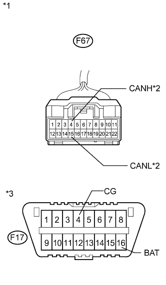
Text in Illustration *1 Front view of wire harness connector
(to CAN No. 3 Junction Connector)
*2 to Seat Belt Control ECU Measure the resistance according to the value(s) in the table below.
Standard Resistance Tester Connection Switch Condition Specified Condition F68-5 (CANH) - F68-16 (CANL) Engine switch off 1 MΩ or higher
NG
REPAIR OR REPLACE CAN NO. 2 BUS BRANCH WIRE OR CONNECTOR (CAN NO. 3 J/C - SEAT BELT CONTROL ECU)
OK
-
-
CHECK FOR SHORT IN CAN NO. 2 BUS WIRE (CAN NO. 3 J/C - PARKING ASSIST ECU)
Tech Tips
For vehicles without parking assist monitor system (w/ side monitor system), go to the next step.
-
Disconnect the parking assist ECU connector.
-
Text in Illustration *1 Front view of wire harness connector
(to CAN No. 3 Junction Connector)
*2 to Parking Assist ECU Measure the resistance according to the value(s) in the table below.
Standard Resistance Tester Connection Switch Condition Specified Condition F68-6 (CANH) - F68-17 (CANL) Engine switch off 1 MΩ or higher
NG
REPAIR OR REPLACE CAN NO. 2 BUS BRANCH WIRE OR CONNECTOR (CAN NO. 3 J/C - PARKING ASSIST ECU)
OK
-
-
CHECK FOR SHORT IN CAN NO. 2 BUS WIRE (CAN NO. 3 J/C - CLEARANCE WARNING ECU)
Tech Tips
For vehicles without LEXUS parking assist-sensor system (w/o side monitor system), go to the next step.
-
Disconnect the clearance warning ECU connector.
-
Text in Illustration *1 Front view of wire harness connector
(to CAN No. 3 Junction Connector)
*2 to Clearance Warning ECU Measure the resistance according to the value(s) in the table below.
Standard Resistance Tester Connection Switch Condition Specified Condition F68-6 (CANH) - F68-17 (CANL) Engine switch off 1 MΩ or higher
NG
REPAIR OR REPLACE CAN NO. 2 BUS BRANCH WIRE OR CONNECTOR (CAN NO. 3 J/C - CLEARANCE WARNING ECU)
OK
-
-
CHECK FOR SHORT IN CAN NO. 2 BUS WIRE (CAN NO. 3 J/C)
-
Reconnect the CAN No. 3 junction connector.
-
Text in Illustration *1 Component with harness connected
(Power Management Control ECU)
Measure the resistance according to the value(s) in the table below.
Note
The resistance must be measured after the main wire connected ECU and junction connector are reconnected.
Standard Resistance Tester Connection Switch Condition Result F8-26 (CA2H) - F8-25 (CA2L) Engine switch off 54 to 69 Ω
NG
REPLACE CAN NO. 3 JUNCTION CONNECTOR
OK
-
-
CHECK FOR SHORT IN CAN NO. 2 BUS WIRE (ECUS)
-
Text in Illustration *1 Component with harness connector
(Power Management Control ECU)
Connect the probes of an ohmmeter to terminals 26 (CA2H) and 25 (CA2L) of the power management control ECU.
-
While observing the resistance value shown on the tester, reconnect each ECU connector until the resistance becomes abnormal (below 54 Ω).
-
Replace the ECU that caused the total resistance to drop below 54 Ω when it was reconnected.
Tech Tips
If the resistance becomes abnormal when an ECU connector is reconnected, there may be a short in the ECU.
NEXT
REPLACE ECU
-
-
CHECK FOR SHORT IN CAN NO. 2 BUS WIRE (CAN NO. 4 J/C)
-
Reconnect the CAN No. 3 junction connector.
-
Text in Illustration *1 Front view of wire harness connector
(to CAN No. 4 Junction Connector)
*2 to CAN No. 5 Junction Connector *3 to CAN No. 3 Junction Connector Disconnect the CAN No. 4 junction connector.
-
Measure the resistance according to the value(s) in the table below.
Standard Resistance Tester Connection Switch Condition Specified Condition Connected to F67-5 (CANH) - F67-16 (CANL) Engine switch off 108 to 132 Ω CAN No. 5 junction connector F67-6 (CANH) - F67-17 (CANL) Engine switch off 108 to 132 Ω CAN No. 3 junction connector Result Result Proceed to OK A NG (to CAN No. 3 junction connector main wire) B NG (to CAN No. 5 junction connector main wire) C
B
REPAIR OR REPLACE CAN BUS MAIN WIRE OR CONNECTOR (CAN NO. 3 J/C - CAN NO. 4 J/C)
C
CHECK FOR SHORT IN CAN NO. 2 BUS WIRE (CAN NO. 5 J/C) Click here
A
-
-
CHECK FOR SHORT IN CAN NO. 2 BUS WIRE (CAN NO. 4 J/C - 4WD CONTROL ECU)
Tech Tips
For 2WD vehicles, go to the next step.
-
Disconnect the 4WD control ECU connector.
-
Text in Illustration *1 Front view of wire harness connector
(to CAN No. 4 Junction Connector)
*2 to 4WD Control ECU Measure the resistance according to the value(s) in the table below.
Standard Resistance Tester Connection Switch Condition Specified Condition F67-1 (CANH) - F67-12 (CANL) Engine switch off 1 MΩ or higher
NG
REPAIR OR REPLACE CAN NO. 2 BUS BRANCH WIRE OR CONNECTOR (CAN NO. 4 J/C - 4WD CONTROL ECU)
OK
-
-
CHECK FOR SHORT IN CAN NO. 2 BUS WIRE (CAN NO. 4 J/C - AFS ECU)
-
Disconnect the AFS ECU connector.
-
Text in Illustration *1 Front view of wire harness connector
(to CAN No. 4 Junction Connector)
*2 to AFS ECU Measure the resistance according to the value(s) in the table below.
Standard Resistance Tester Connection Switch Condition Specified Condition F67-8 (CANH) - F67-19 (CANL) Engine switch off 1 MΩ or higher
NG
REPAIR OR REPLACE CAN NO. 2 BUS BRANCH WIRE OR CONNECTOR (CAN NO. 4 J/C - AFS ECU)
OK
-
-
CHECK FOR SHORT IN CAN NO. 2 BUS WIRE (CAN NO. 4 J/C - DRIVING SUPPORT ECU)
-
Disconnect the driving support ECU connector.
-

Text in Illustration *1 Front view of wire harness connector
(to CAN No. 4 Junction Connector)
*2 to Driving Support ECU Measure the resistance according to the value(s) in the table below.
Standard Resistance Tester Connection Switch Condition Specified Condition F67-7 (CANH) - F67-18 (CANL) Engine switch off 1 MΩ or higher
NG
REPAIR OR REPLACE CAN NO. 2 BUS BRANCH WIRE OR CONNECTOR (CAN NO. 4 J/C - DRIVING SUPPORT ECU)
OK
-
-
CHECK FOR SHORT IN CAN NO. 2 BUS WIRE (CAN NO. 4 J/C)
-
Reconnect the CAN No. 4 junction connector.
-
Text in Illustration *1 Component with harness connector
(Power Management Control ECU)
Measure the resistance according to the value(s) in the table below.
Standard Resistance Tester Connection Switch Condition Result F8-26 (CA2H) - F8-25 (CA2L) Engine switch off 54 to 69 Ω Note
The resistance must be measured after the main wire connected ECU and junction connector are reconnected.
NG
REPLACE CAN NO. 4 JUNCTION CONNECTOR
OK
-
-
CHECK FOR SHORT IN CAN NO. 2 BUS WIRE (ECUS)
-
Text in Illustration *1 Component with harness connector
(Power Management Control ECU)
Connect the probes of an ohmmeter to terminals 26 (CA2H) and 25 (CA2L) of the power management control ECU.
-
While observing the resistance value shown on the tester, reconnect each ECU connector until the resistance becomes abnormal (below 54 Ω).
-
Replace the ECU that caused the total resistance to drop below 54 Ω when it was reconnected.
Tech Tips
If the resistance becomes abnormal when an ECU connector is reconnected, there may be a short in the ECU.
NEXT
REPLACE ECU
-
-
CHECK FOR SHORT IN CAN NO. 2 BUS WIRE (CAN NO. 5 J/C)
-
Reconnect the CAN No. 4 junction connector.
-
Text in Illustration *1 Rear view of wire harness connector
(to CAN No. 5 Junction Connector)
*2 to CAN No. 4 Junction Connector Disconnect the CAN No. 5 junction connector.
-
Measure the resistance according to the value(s) in the table below.
Standard Resistance Tester Connection Switch Condition Specified Condition Connected to F69-3 (CANH) - F69-2 (CANL) Engine switch off 108 to 132 Ω CAN No. 4 junction connector
NG
REPAIR OR REPLACE CAN BUS MAIN WIRE OR CONNECTOR (CAN NO. 4 J/C - CAN NO. 5 J/C)
OK
REPLACE CAN NO. 5 JUNCTION CONNECTOR
-
-
CHECK FOR SHORT IN CAN NO. 2 BUS WIRE (POWER MANAGEMENT CONTROL ECU)
-
Text in Illustration *1 Rear view of wire harness connector
(to Power Management Control ECU)
Disconnect the power management control ECU connector.
-
Measure the resistance according to the value(s) in the table below.
Standard Resistance Tester Connection Condition Specified Condition Purpose F8-26 (CA2H) - F8-6 (GND) Engine switch off 200 Ω or higher Inspection for CANH ground short F8-25 (CA2L) - F8-6 (GND) Engine switch off 200 Ω or higher Inspection for CANL ground short F8-26 (CA2H) - F8-1 (AM22) Cable disconnected from negative (-) battery terminal 6 kΩ or higher Inspection for CANH +B short F8-25 (CA2L) - F8-1 (AM22) Cable disconnected from negative (-) battery terminal 6 kΩ or higher Inspection for CANL +B short Tech Tips
It is only necessary to perform the inspection in the above table for the result (short circuit) that was obtained in the Check CAN Bus Wire inspection.
Find the necessary inspection from the Purpose column that matches the result in the Result column from the Check CAN Bus Wire inspection.
NG
CHECK FOR SHORT IN CAN NO. 2 BUS WIRE (CAN NO. 3 J/C) Click here
OK
REPLACE POWER MANAGEMENT CONTROL ECU
-
-
CHECK FOR SHORT IN CAN NO. 2 BUS WIRE (CAN NO. 3 J/C)
-
Reconnect the power management control ECU connector.
-
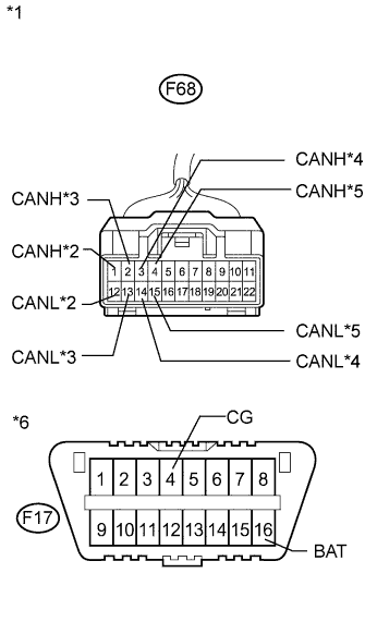
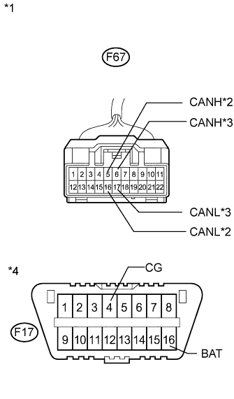
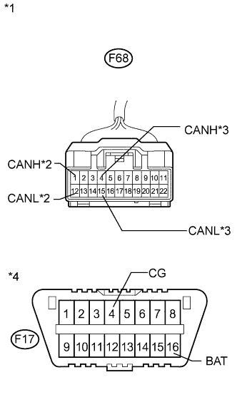
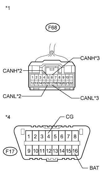
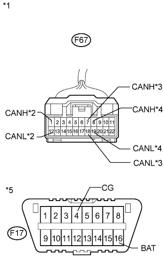
Text in Illustration *1 Front view of wire harness connector
(to CAN No. 3 Junction Connector)
*2 to Power Management Control ECU *3 to Driving Support ECU *4 to AFS ECU *5 to CAN No. 4 Junction Connector *6 DLC3 Disconnect the CAN No. 3 junction connector.
-
Measure the resistance according to the value(s) in the table below.
Standard Resistance Tester Connection Condition Specified Condition Purpose Connected to F68-1 (CANH) - F17-4 (CG) Engine switch off 200 Ω or higher Inspection for CANH ground short Power management control ECU F68-12 (CANL) - F17-4 (CG) Engine switch off 200 Ω or higher Inspection for CANL ground short F68-1 (CANH) - F17-16 (BAT) Cable disconnected from negative (-) battery terminal 6 kΩ or higher Inspection for CANH +B short F68-12 (CANL) - F17-16 (BAT) Cable disconnected from negative (-) battery terminal 6 kΩ or higher Inspection for CANL +B short F68-2 (CANH) - F17-4 (CG) Engine switch off 200 Ω or higher Inspection for CANH ground short Driving support ECU F68-13 (CANL) - F17-4 (CG) Engine switch off 200 Ω or higher Inspection for CANL ground short F68-2 (CANH) - F17-16 (BAT) Cable disconnected from negative (-) battery terminal 6 kΩ or higher Inspection for CANH +B short F68-13 (CANL) - F17-16 (BAT) Cable disconnected from negative (-) battery terminal 6 kΩ or higher Inspection for CANL +B short F68-3 (CANH) - F17-4 (CG) Engine switch off 200 Ω or higher Inspection for CANH ground short AFS ECU F68-14 (CANL) - F17-4 (CG) Engine switch off 200 Ω or higher Inspection for CANL ground short F68-3 (CANH) - F17-16 (BAT) Cable disconnected from negative (-) battery terminal 6 kΩ or higher Inspection for CANH +B short F68-14 (CANL) - F17-16 (BAT) Cable disconnected from negative (-) battery terminal 6 kΩ or higher Inspection for CANL +B short F68-4 (CANH) - F17-4 (CG) Engine switch off 200 Ω or higher Inspection for CANH ground short CAN No. 4 junction connector F68-15 (CANL) - F17-4 (CG) Engine switch off 200 Ω or higher Inspection for CANL ground short F68-4 (CANH) - F17-16 (BAT) Cable disconnected from negative (-) battery terminal 6 kΩ or higher Inspection for CANH +B short F68-15 (CANL) - F17-16 (BAT) Cable disconnected from negative (-) battery terminal 6 kΩ or higher Inspection for CANL +B short Tech Tips
It is only necessary to perform the inspection in the above table for the result (short circuit) that was obtained in the Check CAN Bus Wire inspection.
Find the necessary inspection from the Purpose column that matches the result in the Result column from the Check CAN Bus Wire inspection.
Result Result Proceed to OK A NG (to Power management control ECU main wire) B NG (to CAN No. 4 junction connector main wire) C NG (to AFS ECU branch wire) D NG (to Driving support ECU branch wire) E
B
REPAIR OR REPLACE CAN BUS MAIN WIRE OR CONNECTOR (CAN NO. 3 J/C - POWER MANAGEMENT CONTROL ECU)
C
CHECK FOR SHORT IN CAN NO. 2 BUS WIRE (CAN NO. 4 J/C MAIN WIRE) Click here
D
CHECK FOR SHORT IN CAN NO. 2 BUS WIRE (AFS ECU) Click here
E
CHECK FOR SHORT IN CAN NO. 2 BUS WIRE (DRIVING SUPPORT ECU) Click here
A
REPLACE CAN NO. 3 JUNCTION CONNECTOR
-
-
CHECK FOR SHORT IN CAN NO. 2 BUS WIRE (CAN NO. 4 J/C MAIN WIRE)
-
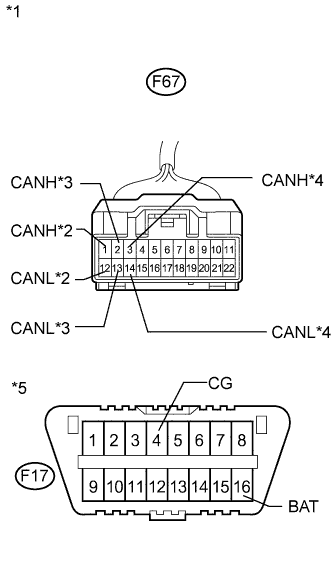
Text in Illustration *1 Front view of wire harness connector
(to CAN No. 4 Junction Connector)
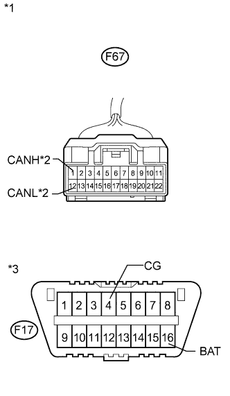
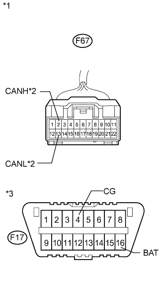
*2 to CAN No. 5 Junction Connector *3 to CAN No. 3 Junction Connector *4 DLC3 Disconnect the CAN No. 4 junction connector.
-
Measure the resistance according to the value(s) in the table below.
Standard Resistance Tester Connection Condition Specified Condition Purpose Connected to F67-5 (CANH) - F17-4 (CG) Engine switch off 200 Ω or higher Inspection for CANH ground short CAN No. 5 junction connector F67-16 (CANL) - F17-4 (CG) Engine switch off 200 Ω or higher Inspection for CANL ground short F67-5 (CANH) - F17-16 (BAT) Cable disconnected from negative (-) battery terminal 6 kΩ or higher Inspection for CANH +B short F67-16 (CANL) - F17-16 (BAT) Cable disconnected from negative (-) battery terminal 6 kΩ or higher Inspection for CANL +B short F67-6 (CANH) - F17-4 (CG) Engine switch off 200 Ω or higher Inspection for CANH ground short CAN No. 3 junction connector F67-17 (CANL) - F17-4 (CG) Engine switch off 200 Ω or higher Inspection for CANL ground short F67-6 (CANH) - F17-16 (BAT) Cable disconnected from negative (-) battery terminal 6 kΩ or higher Inspection for CANH +B short F67-17 (CANL) - F17-16 (BAT) Cable disconnected from negative (-) battery terminal 6 kΩ or higher Inspection for CANL +B short Tech Tips
It is only necessary to perform the inspection in the above table for the result (short circuit) that was obtained in the Check CAN Bus Wire inspection.
Find the necessary inspection from the Purpose column that matches the result in the Result column from the Check CAN Bus Wire inspection.
Result Result Proceed to OK A NG (to CAN No. 3 junction connector main wire) B NG (to CAN No. 5 junction connector main wire) C
B
REPAIR OR REPLACE CAN BUS MAIN WIRE OR CONNECTOR (CAN NO. 3 J/C - CAN NO. 4 J/C)
C
CHECK FOR SHORT IN CAN NO. 2 BUS WIRE (CAN NO. 5 J/C) Click here
A
-
-
CHECK FOR SHORT IN CAN NO. 2 BUS WIRE (CAN NO. 4 J/C BRANCH WIRE)
-
Measure the resistance according to the value(s) in the table below.
Standard Resistance Tester Connection Condition Specified Condition Purpose Connected to F67-1 (CANH) - F17-4 (CG) Engine switch off 200 Ω or higher Inspection for CANH ground short 4WD control ECU* F67-12 (CANL) - F17-4 (CG) Engine switch off 200 Ω or higher Inspection for CANL ground short F67-1 (CANH) - F17-16 (BAT) Cable disconnected from negative (-) battery terminal 6 kΩ or higher Inspection for CANH +B short F67-12 (CANL) - F17-16 (BAT) Cable disconnected from negative (-) battery terminal 6 kΩ or higher Inspection for CANL +B short F67-2 (CANH) - F17-4 (CG) Engine switch off 200 Ω or higher Inspection for CANH ground short Suspension control ECU F67-13 (CANL) - F17-4 (CG) Engine switch off 200 Ω or higher Inspection for CANL ground short F67-2 (CANH) - F17-16 (BAT) Cable disconnected from negative (-) battery terminal 6 kΩ or higher Inspection for CANH +B short F67-13 (CANL) - F17-16 (BAT) Cable disconnected from negative (-) battery terminal 6 kΩ or higher Inspection for CANL +B short F67-3 (CANH) - F17-4 (CG) Engine switch off 200 Ω or higher Inspection for CANH ground short Seat belt control ECU F67-14 (CANL) - F17-4 (CG) Engine switch off 200 Ω or higher Inspection for CANL ground short F67-3 (CANH) - F17-16 (BAT) Cable disconnected from negative (-) battery terminal 6 kΩ or higher Inspection for CANH +B short F67-14 (CANL) - F17-16 (BAT) Cable disconnected from negative (-) battery terminal 6 kΩ or higher Inspection for CANL +B short Text in Illustration *1 Front view of wire harness connector
(to CAN No. 4 Junction Connector)
*2 to 4WD Control ECU (for AWD) *3 to Suspension Control ECU *4 to Seat Belt Control ECU *5 DLC3 Tech Tips
-
It is only necessary to perform the inspection in the above table for the result (short circuit) that was obtained in the Check CAN Bus Wire inspection. Find the necessary inspection from the Purpose column that matches the result in the Result column from the Check CAN Bus Wire inspection.
-
*: for AWD
Result Result Proceed to OK (w/ parking assist monitor system or LEXUS parking assist-sensor system) A OK (w/o parking assist monitor system or LEXUS parking assist-sensor system) B NG (to 4WD control ECU branch wire) C NG (to Suspension control ECU branch wire) D NG (to Seat belt control ECU branch wire) E -
B
REPLACE CAN NO. 4 JUNCTION CONNECTOR
C
CHECK FOR SHORT IN CAN NO. 2 BUS WIRE (4WD CONTROL ECU) Click here
D
CHECK FOR SHORT IN CAN NO. 2 BUS WIRE (SUSPENSION CONTROL ECU) Click here
E
CHECK FOR SHORT IN CAN NO. 2 BUS WIRE (SEAT BELT CONTROL ECU) Click here
A
-
-
CHECK FOR SHORT IN CAN NO. 2 BUS WIRE (CAN NO. 4 J/C BRANCH WIRE)
-
Measure the resistance according to the value(s) in the table below.
Standard Resistance Tester Connection Condition Specified Condition Purpose Connected to F67-4 (CANH) - F17-4 (CG) Engine switch off 200 Ω or higher Inspection for CANH ground short Parking assist ECU
or
Clearance warning ECU
F67-15 (CANL) - F17-4 (CG) Engine switch off 200 Ω or higher Inspection for CANL ground short F67-4 (CANH) - F17-16 (BAT) Cable disconnected from negative (-) battery terminal 6 kΩ or higher Inspection for CANH +B short F67-15 (CANL) - F17-16 (BAT) Cable disconnected from negative (-) battery terminal 6 kΩ or higher Inspection for CANL +B short Text in Illustration *1 Front view of wire harness connector
(to CAN No. 4 Junction Connector)
*2 to Parking Assist ECU or Clearance Warning ECU *3 DLC3 Tech Tips
It is only necessary to perform the inspection in the above table for the result (short circuit) that was obtained in the Check CAN Bus Wire inspection.
Find the necessary inspection from the Purpose column that matches the result in the Result column from the Check CAN Bus Wire inspection.
Result Result Proceed to OK A NG (to Parking assist ECU branch wire) B NG (to Clearance warning ECU branch wire) C
B
CHECK FOR SHORT IN CAN NO. 2 BUS WIRE (PARKING ASSIST ECU) Click here
C
CHECK FOR SHORT IN CAN NO. 2 BUS WIRE (CLEARANCE WARNING ECU) Click here
A
REPLACE CAN NO. 4 JUNCTION CONNECTOR
-
-
CHECK FOR SHORT IN CAN NO. 2 BUS WIRE (CAN NO. 5 J/C)
-
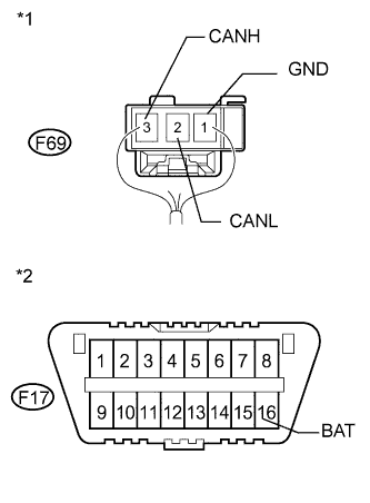
Text in Illustration *1 Rear view of wire harness connector
(to CAN No. 5 Junction Connector)
*2 DLC3 Disconnect the CAN No. 5 junction connector.
-
Measure the resistance according to the value(s) in the table below.
Standard Resistance Tester Connection Condition Specified Condition Purpose Connected to F69-3 (CANH) - F69-1 (GND) Engine switch off 200 Ω or higher Inspection for CANH ground short CAN No. 4 junction connector F69-2 (CANL) - F69-1 (GND) Engine switch off 200 Ω or higher Inspection for CANL ground short F69-3 (CANH) - F17-16 (BAT) Cable disconnected from negative (-) battery terminal 6 kΩ or higher Inspection for CANH +B short F69-2 (CANL) - F17-16 (BAT) Cable disconnected from negative (-) battery terminal 6 kΩ or higher Inspection for CANL +B short Tech Tips
It is only necessary to perform the inspection in the above table for the result (short circuit) that was obtained in the Check CAN Bus Wire inspection.
Find the necessary inspection from the Purpose column that matches the result in the Result column from the Check CAN Bus Wire inspection.
NG
REPAIR OR REPLACE CAN BUS MAIN WIRE OR CONNECTOR (CAN NO. 4 J/C - CAN NO. 5 J/C)
OK
REPLACE CAN NO. 5 JUNCTION CONNECTOR
-
-
CHECK FOR SHORT IN CAN NO. 2 BUS WIRE (AFS ECU)
-
Disconnect the AFS ECU connector.
-

Text in Illustration *1 Front view of wire harness connector
(to CAN No. 3 Junction Connector)
*2 to AFS ECU *3 DLC3 Measure the resistance according to the value(s) in the table below.
Standard Resistance Tester Connection Condition Specified Condition Purpose F68-3 (CANH) - F17-4 (CG) Engine switch off 200 Ω or higher Inspection for CANH ground short F68-14 (CANL) - F17-4 (CG) Engine switch off 200 Ω or higher Inspection for CANL ground short F68-3 (CANH) - F17-16 (BAT) Cable disconnected from negative (-) battery terminal 6 kΩ or higher Inspection for CANH +B short F68-14 (CANL) - F17-16 (BAT) Cable disconnected from negative (-) battery terminal 6 kΩ or higher Inspection for CANL +B short Tech Tips
It is only necessary to perform the inspection in the above table for the result (short circuit) that was obtained in the Check CAN Bus Wire inspection.
Find the necessary inspection from the Purpose column that matches the result in the Result column from the Check CAN Bus Wire inspection.
NG
REPAIR OR REPLACE CAN NO. 2 BUS BRANCH WIRE OR CONNECTOR (CAN NO. 3 J/C - AFS ECU)
OK
REPLACE HEADLIGHT SWIVEL ECU (AFS ECU)
-
-
CHECK FOR SHORT IN CAN NO. 2 BUS WIRE (DRIVING SUPPORT ECU)
-
Disconnect the driving support ECU connector.
-

Text in Illustration *1 Front view of wire harness connector
(to CAN No. 3 Junction Connector)
*2 to Driving Support ECU *3 DLC3 Measure the resistance according to the value(s) in the table below.
Standard Resistance Tester Connection Condition Specified Condition Purpose F68-2 (CANH) - F17-4 (CG) Engine switch off 200 Ω or higher Inspection for CANH ground short F68-13 (CANL) - F17-4 (CG) Engine switch off 200 Ω or higher Inspection for CANL ground short F68-2 (CANH) - F17-16 (BAT) Cable disconnected from negative (-) battery terminal 6 kΩ or higher Inspection for CANH +B short F68-13 (CANL) - F17-16 (BAT) Cable disconnected from negative (-) battery terminal 6 kΩ or higher Inspection for CANL +B short Tech Tips
It is only necessary to perform the inspection in the above table for the result (short circuit) that was obtained in the Check CAN Bus Wire inspection.
Find the necessary inspection from the Purpose column that matches the result in the Result column from the Check CAN Bus Wire inspection.
NG
REPAIR OR REPLACE CAN NO. 2 BUS BRANCH WIRE OR CONNECTOR (CAN NO. 3 J/C - DRIVING SUPPORT ECU)
OK
REPLACE DRIVING SUPPORT ECU
-
-
CHECK FOR SHORT IN CAN NO. 2 BUS WIRE (4WD CONTROL ECU)
-
Disconnect the 4WD control ECU connector.
-
Text in Illustration *1 Front view of wire harness connector
(to CAN No. 4 Junction Connector)
*2 to 4WD Control ECU *3 DLC3 Measure the resistance according to the value(s) in the table below.
Standard Resistance Tester Connection Condition Specified Condition Purpose F67-1 (CANH) - F17-4 (CG) Engine switch off 200 Ω or higher Inspection for CANH ground short F67-12 (CANL) - F17-4 (CG) Engine switch off 200 Ω or higher Inspection for CANL ground short F67-1 (CANH) - F17-16 (BAT) Cable disconnected from negative (-) battery terminal 6 kΩ or higher Inspection for CANH +B short F67-12 (CANL) - F17-16 (BAT) Cable disconnected from negative (-) battery terminal 6 kΩ or higher Inspection for CANL +B short Tech Tips
It is only necessary to perform the inspection in the above table for the result (short circuit) that was obtained in the Check CAN Bus Wire inspection.
Find the necessary inspection from the Purpose column that matches the result in the Result column from the Check CAN Bus Wire inspection.
NG
REPAIR OR REPLACE CAN NO. 2 BUS BRANCH WIRE OR CONNECTOR (CAN NO. 4 J/C - 4WD CONTROL ECU)
OK
REPLACE 4WD CONTROL ECU
-
-
CHECK FOR SHORT IN CAN NO. 2 BUS WIRE (SUSPENSION CONTROL ECU)
-
Disconnect the suspension control ECU connector.
-
Text in Illustration *1 Front view of wire harness connector
(to CAN No. 4 Junction Connector)
*2 to Suspension Control ECU *3 DLC3 Measure the resistance according to the value(s) in the table below.
Standard Resistance Tester Connection Condition Specified Condition Purpose F67-2 (CANH) - F17-4 (CG) Engine switch off 200 Ω or higher Inspection for CANH ground short F67-13 (CANL) - F17-4 (CG) Engine switch off 200 Ω or higher Inspection for CANL ground short F67-2 (CANH) - F17-16 (BAT) Cable disconnected from negative (-) battery terminal 6 kΩ or higher Inspection for CANH +B short F67-13 (CANL) - F17-16 (BAT) Cable disconnected from negative (-) battery terminal 6 kΩ or higher Inspection for CANL +B short Tech Tips
It is only necessary to perform the inspection in the above table for the result (short circuit) that was obtained in the Check CAN Bus Wire inspection.
Find the necessary inspection from the Purpose column that matches the result in the Result column from the Check CAN Bus Wire inspection.
NG
REPAIR OR REPLACE CAN NO. 2 BUS BRANCH WIRE OR CONNECTOR (CAN NO. 4 J/C - SUSPENSION CONTROL ECU)
OK
REPLACE SUSPENSION CONTROL ECU
-
-
CHECK FOR SHORT IN CAN NO. 2 BUS WIRE (SEAT BELT CONTROL ECU)
-
Disconnect the seat belt control ECU connector.
-

Text in Illustration *1 Front view of wire harness connector
(to CAN No. 4 Junction Connector)
*2 to Seat Belt Control ECU *3 DLC3 Measure the resistance according to the value(s) in the table below.
Standard Resistance Tester Connection Switch Condition Specified Condition Purpose F67-3 (CANH) - F17-4 (CG) Engine switch off 200 Ω or higher Inspection for CANH ground short F67-14 (CANL) - F17-4 (CG) Engine switch off 200 Ω or higher Inspection for CANL ground short F67-3 (CANH) - F17-16 (BAT) Cable disconnected from negative (-) battery terminal 6 kΩ or higher Inspection for CANH +B short F67-14 (CANL) - F17-16 (BAT) Cable disconnected from negative (-) battery terminal 6 kΩ or higher Inspection for CANL +B short Tech Tips
It is only necessary to perform the inspection in the above table for the result (short circuit) that was obtained in the Check CAN Bus Wire inspection.
Find the necessary inspection from the Purpose column that matches the result in the Result column from the Check CAN Bus Wire inspection.
NG
REPAIR OR REPLACE CAN NO. 2 BUS BRANCH WIRE OR CONNECTOR (CAN NO. 4 J/C - SEAT BELT CONTROL ECU)
OK
REPLACE SEAT BELT CONTROL ECU
-
-
CHECK FOR SHORT IN CAN NO. 2 BUS WIRE (PARKING ASSIST ECU)
-
Disconnect the parking assist ECU connector.
-
Text in Illustration *1 Front view of wire harness connector
(to CAN No. 4 Junction Connector)
*2 to Parking Assist ECU *3 DLC3 Measure the resistance according to the value(s) in the table below.
Standard Resistance Tester Connection Condition Specified Condition Purpose F67-4 (CANH) - F17-4 (CG) Engine switch off 200 Ω or higher Inspection for CANH ground short F67-15 (CANL) - F17-4 (CG) Engine switch off 200 Ω or higher Inspection for CANL ground short F67-4 (CANH) - F17-16 (BAT) Cable disconnected from negative (-) battery terminal 6 kΩ or higher Inspection for CANH +B short F67-15 (CANL) - F17-16 (BAT) Cable disconnected from negative (-) battery terminal 6 kΩ or higher Inspection for CANL +B short Tech Tips
It is only necessary to perform the inspection in the above table for the result (short circuit) that was obtained in the Check CAN Bus Wire inspection.
Find the necessary inspection from the Purpose column that matches the result in the Result column from the Check CAN Bus Wire inspection.
NG
REPAIR OR REPLACE CAN NO. 2 BUS BRANCH WIRE OR CONNECTOR (CAN NO. 4 J/C - PARKING ASSIST ECU)
OK
REPLACE PARKING ASSIST ECU
-
-
CHECK FOR SHORT IN CAN NO. 2 BUS WIRE (CLEARANCE WARNING ECU)
-
Disconnect the clearance warning ECU connector.
-
Text in Illustration *1 Front view of wire harness connector
(to CAN No. 4 Junction Connector)
*2 to Clearance Warning ECU *3 DLC3 Measure the resistance according to the value(s) in the table below.
Standard Resistance Tester Connection Condition Specified Condition Purpose F67-4 (CANH) - F17-4 (CG) Engine switch off 200 Ω or higher Inspection for CANH ground short F67-15 (CANL) - F17-4 (CG) Engine switch off 200 Ω or higher Inspection for CANL ground short F67-4 (CANH) - F17-16 (BAT) Cable disconnected from negative (-) battery terminal 6 kΩ or higher Inspection for CANH +B short F67-15 (CANL) - F17-16 (BAT) Cable disconnected from negative (-) battery terminal 6 kΩ or higher Inspection for CANL +B short Tech Tips
It is only necessary to perform the inspection in the above table for the result (short circuit) that was obtained in the Check CAN Bus Wire inspection.
Find the necessary inspection from the Purpose column that matches the result in the Result column from the Check CAN Bus Wire inspection.
NG
REPAIR OR REPLACE CAN NO. 2 BUS BRANCH WIRE OR CONNECTOR (CAN NO. 4 J/C - CLEARANCE WARNING ECU)
OK
REPLACE CLEARANCE WARNING ECU
-
-
CHECK FOR SHORT IN CAN NO. 2 BUS WIRE (POWER MANAGEMENT CONTROL ECU)
-
Text in Illustration *1 Rear view of wire harness connector
(to Power Management Control ECU)
Disconnect the power management control ECU connector.
-
Measure the resistance according to the value(s) in the table below.
Standard Resistance Tester Connection Condition Specified Condition Purpose F8-26 (CA2H) - F8-6 (GND) Engine switch off 200 Ω or higher Inspection for CANH ground short F8-25 (CA2L) - F8-6 (GND) Engine switch off 200 Ω or higher Inspection for CANL ground short F8-26 (CA2H) - F8-1 (AM22) Cable disconnected from negative (-) battery terminal 6 kΩ or higher Inspection for CANH +B short F8-25 (CA2L) - F8-1 (AM22) Cable disconnected from negative (-) battery terminal 6 kΩ or higher Inspection for CANL +B short Tech Tips
It is only necessary to perform the inspection in the above table for the result (short circuit) that was obtained in the Check CAN Bus Wire inspection.
Find the necessary inspection from the Purpose column that matches the result in the Result column from the Check CAN Bus Wire inspection.
NG
CHECK FOR SHORT IN CAN NO. 2 BUS WIRE (CAN NO. 3 J/C MAIN WIRE) Click here
OK
REPLACE POWER MANAGEMENT CONTROL ECU
-
-
CHECK FOR SHORT IN CAN NO. 2 BUS WIRE (CAN NO. 3 J/C MAIN WIRE)
-
Reconnect the power management control ECU connector.
-
Text in Illustration *1 Front view of wire harness connector
(to CAN No. 3 Junction Connector)
*2 to Power Management Control ECU *3 to CAN No. 4 Junction Connector *4 DLC3 Disconnect the CAN No. 3 junction connector.
-
Measure the resistance according to the value(s) in the table below.
Standard Resistance Tester Connection Condition Specified Condition Purpose Connected to F68-1 (CANH) - F17-4 (CG) Engine switch off 200 Ω or higher Inspection for CANH ground short Power management control ECU F68-12 (CANL) - F17-4 (CG) Engine switch off 200 Ω or higher Inspection for CANL ground short F68-1 (CANH) - F17-16 (BAT) Cable disconnected from negative (-) battery terminal 6 kΩ or higher Inspection for CANH +B short F68-12 (CANL) - F17-16 (BAT) Cable disconnected from negative (-) battery terminal 6 kΩ or higher Inspection for CANL +B short F68-4 (CANH) - F17-4 (CG) Engine switch off 200 Ω or higher Inspection for CANH ground short CAN No. 4 junction connector F68-15 (CANL) - F17-4 (CG) Engine switch off 200 Ω or higher Inspection for CANL ground short F68-4 (CANH) - F17-16 (BAT) Cable disconnected from negative (-) battery terminal 6 kΩ or higher Inspection for CANH +B short F68-15 (CANL) - F17-16 (BAT) Cable disconnected from negative (-) battery terminal 6 kΩ or higher Inspection for CANL +B short Tech Tips
It is only necessary to perform the inspection in the above table for the result (short circuit) that was obtained in the Check CAN Bus Wire inspection.
Find the necessary inspection from the Purpose column that matches the result in the Result column from the Check CAN Bus Wire inspection.
Result Result Proceed to OK A NG (to Power management control ECU main wire) B NG (to CAN No. 4 junction connector main wire) C
B
REPAIR OR REPLACE CAN BUS MAIN WIRE OR CONNECTOR (CAN NO. 3 J/C - POWER MANAGEMENT CONTROL ECU)
C
CHECK FOR SHORT IN CAN NO. 2 BUS WIRE (CAN NO. 4 J/C MAIN WIRE) Click here
A
-
-
CHECK FOR SHORT IN CAN NO. 2 BUS WIRE (CAN NO. 3 J/C BRANCH WIRE)
-
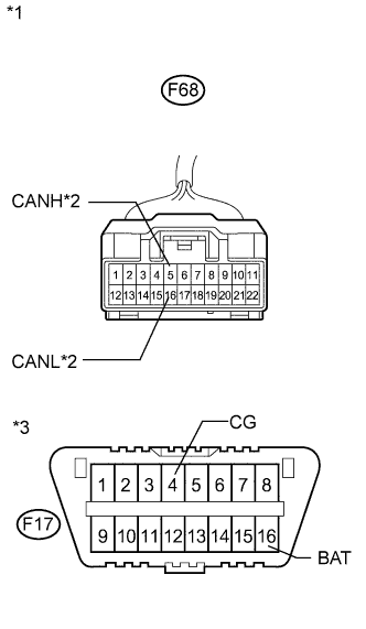
Text in Illustration *1 Front view of wire harness connector
(to CAN No. 3 Junction Connector)
*2 to Seat Belt Control ECU *3 to Parking Assist ECU or Clearance Warning ECU *4 DLC3 Measure the resistance according to the value(s) in the table below.
Standard Resistance Tester Connection Condition Specified Condition Purpose Connected to F68-5 (CANH) - F17-4 (CG) Engine switch off 200 Ω or higher Inspection for CANH ground short Seat belt control ECU F68-16 (CANL) - F17-4 (CG) Engine switch off 200 Ω or higher Inspection for CANL ground short F68-5 (CANH) - F17-16 (BAT) Cable disconnected from negative (-) battery terminal 6 kΩ or higher Inspection for CANH +B short F68-16 (CANL) - F17-16 (BAT) Cable disconnected from negative (-) battery terminal 6 kΩ or higher Inspection for CANL +B short F68-6 (CANH) - F17-4 (CG) Engine switch off 200 Ω or higher Inspection for CANH ground short Parking assist ECU
or
Clearance warning ECU
F68-17 (CANL) - F17-4 (CG) Engine switch off 200 Ω or higher Inspection for CANL ground short F68-6 (CANH) - F17-16 (BAT) Cable disconnected from negative (-) battery terminal 6 kΩ or higher Inspection for CANH +B short F68-17 (CANL) - F17-16 (BAT) Cable disconnected from negative (-) battery terminal 6 kΩ or higher Inspection for CANL +B short Tech Tips
It is only necessary to perform the inspection in the above table for the result (short circuit) that was obtained in the Check CAN Bus Wire inspection.
Find the necessary inspection from the Purpose column that matches the result in the Result column from the Check CAN Bus Wire inspection.
Result Result Proceed to OK A NG (to Seat belt control ECU branch wire) B NG (to Parking assist ECU branch wire) C NG (to Clearance warning ECU branch wire) D
B
CHECK FOR SHORT IN CAN NO. 2 BUS WIRE (SEAT BELT CONTROL ECU) Click here
C
CHECK FOR SHORT IN CAN NO. 2 BUS WIRE (PARKING ASSIST ECU) Click here
D
CHECK FOR SHORT IN CAN NO. 2 BUS WIRE (CLEARANCE WARNING ECU) Click here
A
REPLACE CAN NO. 3 JUNCTION CONNECTOR
-
-
CHECK FOR SHORT IN CAN NO. 2 BUS WIRE (CAN NO. 4 J/C MAIN WIRE)
-
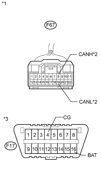
Text in Illustration *1 Front view of wire harness connector
(to CAN No. 4 Junction Connector)
*2 to CAN No. 5 Junction Connector *3 to CAN No. 3 Junction Connector *4 DLC3 Disconnect the CAN No. 4 junction connector.
-
Measure the resistance according to the value(s) in the table below.
Standard Resistance Tester Connection Condition Specified Condition Purpose Connected to F67-5 (CANH) - F17-4 (CG) Engine switch off 200 Ω or higher Inspection for CANH ground short CAN No. 5 junction connector F67-16 (CANL) - F17-4 (CG) Engine switch off 200 Ω or higher Inspection for CANL ground short F67-5 (CANH) - F17-16 (BAT) Cable disconnected from negative (-) battery terminal 6 kΩ or higher Inspection for CANH +B short F67-16 (CANL) - F17-16 (BAT) Cable disconnected from negative (-) battery terminal 6 kΩ or higher Inspection for CANL +B short F67-6 (CANH) - F17-4 (CG) Engine switch off 200 Ω or higher Inspection for CANH ground short CAN No. 3 junction connector F67-17 (CANL) - F17-4 (CG) Engine switch off 200 Ω or higher Inspection for CANL ground short F67-6 (CANH) - F17-16 (BAT) Cable disconnected from negative (-) battery terminal 6 kΩ or higher Inspection for CANH +B short F67-17 (CANL) - F17-16 (BAT) Cable disconnected from negative (-) battery terminal 6 kΩ or higher Inspection for CANL +B short Tech Tips
It is only necessary to perform the inspection in the above table for the result (short circuit) that was obtained in the Check CAN Bus Wire inspection.
Find the necessary inspection from the Purpose column that matches the result in the Result column from the Check CAN Bus Wire inspection.
Result Result Proceed to OK A NG (to CAN No. 3 junction connector main wire) B NG (to CAN No. 5 junction connector main wire) C
B
REPAIR OR REPLACE CAN BUS MAIN WIRE OR CONNECTOR (CAN NO. 3 J/C - CAN NO. 4 J/C)
C
CHECK FOR SHORT IN CAN NO. 2 BUS WIRE (CAN NO. 5 J/C) Click here
A
-
-
CHECK FOR SHORT IN CAN NO. 2 BUS WIRE (CAN NO. 4 J/C BRANCH WIRE)
-
Measure the resistance according to the value(s) in the table below.
Standard Resistance Tester Connection Condition Specified Condition Purpose Connected to F67-1 (CANH) - F17-4 (CG) Engine switch off 200 Ω or higher Inspection for CANH ground short 4WD control ECU* F67-12 (CANL) - F17-4 (CG) Engine switch off 200 Ω or higher Inspection for CANL ground short F67-1 (CANH) - F17-16 (BAT) Cable disconnected from negative (-) battery terminal 6 kΩ or higher Inspection for CANH +B short F67-12 (CANL) - F17-16 (BAT) Cable disconnected from negative (-) battery terminal 6 kΩ or higher Inspection for CANL +B short F67-7 (CANH) - F17-4 (CG) Engine switch off 200 Ω or higher Inspection for CANH ground short Driving support ECU F67-18 (CANL) - F17-4 (CG) Engine switch off 200 Ω or higher Inspection for CANL ground short F67-7 (CANH) - F17-16 (BAT) Cable disconnected from negative (-) battery terminal 6 kΩ or higher Inspection for CANH +B short F67-18 (CANL) - F17-16 (BAT) Cable disconnected from negative (-) battery terminal 6 kΩ or higher Inspection for CANL +B short F67-8 (CANH) - F17-4 (CG) Engine switch off 200 Ω or higher Inspection for CANH ground short AFS ECU F67-19 (CANL) - F17-4 (CG) Engine switch off 200 Ω or higher Inspection for CANL ground short F67-8 (CANH) - F17-16 (BAT) Cable disconnected from negative (-) battery terminal 6 kΩ or higher Inspection for CANH +B short F67-19 (CANL) - F17-16 (BAT) Cable disconnected from negative (-) battery terminal 6 kΩ or higher Inspection for CANL +B short Text in Illustration *1 Front view of wire harness connector
(to CAN No. 4 Junction Connector)
*2 to 4WD Control ECU (for AWD) *3 to Driving Support ECU *4 to AFS ECU *5 DLC3 Tech Tips
-
It is only necessary to perform the inspection in the above table for the result (short circuit) that was obtained in the Check CAN Bus Wire inspection. Find the necessary inspection from the Purpose column that matches the result in the Result column from the Check CAN Bus Wire inspection.
-
*: for AWD
Result Result Proceed to OK A NG (to 4WD control ECU branch wire) B NG (to AFS ECU branch wire) C NG (to Driving support ECU branch wire) D -
B
CHECK FOR SHORT IN CAN NO. 2 BUS WIRE (4WD CONTROL ECU) Click here
C
CHECK FOR SHORT IN CAN NO. 2 BUS WIRE (AFS ECU) Click here
D
CHECK FOR SHORT IN CAN NO. 2 BUS WIRE (DRIVING SUPPORT ECU) Click here
A
REPLACE CAN NO. 4 JUNCTION CONNECTOR
-
-
CHECK FOR SHORT IN CAN NO. 2 BUS WIRE (CAN NO. 5 J/C)
-
Text in Illustration *1 Rear view of wire harness connector
(to CAN No. 5 Junction Connector)
*2 DLC3 Disconnect the CAN No. 5 junction connector.
-
Measure the resistance according to the value(s) in the table below.
Standard Resistance Tester Connection Condition Specified Condition Purpose Connected to F69-3 (CANH) - F69-1 (GND) Engine switch off 200 Ω or higher Inspection for CANH ground short CAN No. 4 junction connector F69-2 (CANL) - F69-1 (GND) Engine switch off 200 Ω or higher Inspection for CANL ground short F69-3 (CANH) - F17-16 (BAT) Cable disconnected from negative (-) battery terminal 6 kΩ or higher Inspection for CANH +B short F69-2 (CANL) - F17-16 (BAT) Cable disconnected from negative (-) battery terminal 6 kΩ or higher Inspection for CANL +B short Tech Tips
It is only necessary to perform the inspection in the above table for the result (short circuit) that was obtained in the Check CAN Bus Wire inspection.
Find the necessary inspection from the Purpose column that matches the result in the Result column from the Check CAN Bus Wire inspection.
NG
REPAIR OR REPLACE CAN BUS MAIN WIRE OR CONNECTOR (CAN NO. 4 J/C - CAN NO. 5 J/C)
OK
REPLACE CAN NO. 5 JUNCTION CONNECTOR
-
-
CHECK FOR SHORT IN CAN NO. 2 BUS WIRE (SEAT BELT CONTROL ECU)
-
Disconnect the seat belt control ECU connector.
-
Text in Illustration *1 Front view of wire harness connector
(to CAN No. 3 Junction Connector)
*2 to Seat Belt Control ECU *3 DLC3 Measure the resistance according to the value(s) in the table below.
Standard Resistance Tester Connection Switch Condition Specified Condition Purpose F68-5 (CANH) - F17-4 (CG) Engine switch off 200 Ω or higher Inspection for CANH ground short F68-16 (CANL) - F17-4 (CG) Engine switch off 200 Ω or higher Inspection for CANL ground short F68-5 (CANH) - F17-16 (BAT) Cable disconnected from negative (-) battery terminal 6 kΩ or higher Inspection for CANH +B short F67-16 (CANL) - F17-16 (BAT) Cable disconnected from negative (-) battery terminal 6 kΩ or higher Inspection for CANL +B short Tech Tips
It is only necessary to perform the inspection in the above table for the result (short circuit) that was obtained in the Check CAN Bus Wire inspection.
Find the necessary inspection from the Purpose column that matches the result in the Result column from the Check CAN Bus Wire inspection.
NG
REPAIR OR REPLACE CAN NO. 2 BUS BRANCH WIRE OR CONNECTOR (CAN NO. 3 J/C - SEAT BELT CONTROL ECU)
OK
REPLACE SEAT BELT CONTROL ECU
-
-
CHECK FOR SHORT IN CAN NO. 2 BUS WIRE (PARKING ASSIST ECU)
-
Disconnect the parking assist ECU connector.
-

Text in Illustration *1 Front view of wire harness connector
(to CAN No. 3 Junction Connector)
*2 to Parking Assist ECU *3 DLC3 Measure the resistance according to the value(s) in the table below.
Standard Resistance Tester Connection Condition Specified Condition Purpose F68-6 (CANH) - F17-4 (CG) Engine switch off 200 Ω or higher Inspection for CANH ground short F68-17 (CANL) - F17-4 (CG) Engine switch off 200 Ω or higher Inspection for CANL ground short F68-6 (CANH) - F17-16 (BAT) Cable disconnected from negative (-) battery terminal 6 kΩ or higher Inspection for CANH +B short F68-17 (CANL) - F17-16 (BAT) Cable disconnected from negative (-) battery terminal 6 kΩ or higher Inspection for CANL +B short Tech Tips
It is only necessary to perform the inspection in the above table for the result (short circuit) that was obtained in the Check CAN Bus Wire inspection.
Find the necessary inspection from the Purpose column that matches the result in the Result column from the Check CAN Bus Wire inspection.
NG
REPAIR OR REPLACE CAN NO. 2 BUS BRANCH WIRE OR CONNECTOR (CAN NO. 3 J/C - PARKING ASSIST ECU)
OK
REPLACE PARKING ASSIST ECU
-
-
CHECK FOR SHORT IN CAN NO. 2 BUS WIRE (CLEARANCE WARNING ECU)
-
Disconnect the clearance warning ECU connector.
-
Text in Illustration *1 Front view of wire harness connector
(to CAN No. 3 Junction Connector)
*2 to Clearance Warning ECU *3 DLC3 Measure the resistance according to the value(s) in the table below.
Standard Resistance Tester Connection Condition Specified Condition Purpose F68-6 (CANH) - F17-4 (CG) Engine switch off 200 Ω or higher Inspection for CANH ground short F68-17 (CANL) - F17-4 (CG) Engine switch off 200 Ω or higher Inspection for CANL ground short F68-6 (CANH) - F17-16 (BAT) Cable disconnected from negative (-) battery terminal 6 kΩ or higher Inspection for CANH +B short F68-17 (CANL) - F17-16 (BAT) Cable disconnected from negative (-) battery terminal 6 kΩ or higher Inspection for CANL +B short Tech Tips
It is only necessary to perform the inspection in the above table for the result (short circuit) that was obtained in the Check CAN Bus Wire inspection.
Find the necessary inspection from the Purpose column that matches the result in the Result column from the Check CAN Bus Wire inspection.
NG
REPAIR OR REPLACE CAN NO. 2 BUS BRANCH WIRE OR CONNECTOR (CAN NO. 3 J/C - CLEARANCE WARNING ECU)
OK
REPLACE CLEARANCE WARNING ECU
-
-
CHECK FOR SHORT IN CAN NO. 2 BUS WIRE (4WD CONTROL ECU)
-
Disconnect the 4WD control ECU connector.
-
Text in Illustration *1 Front view of wire harness connector
(to CAN No. 4 Junction Connector)
*2 to 4WD Control ECU *3 DLC3 Measure the resistance according to the value(s) in the table below.
Standard Resistance Tester Connection Condition Specified Condition Purpose F67-1 (CANH) - F17-4 (CG) Engine switch off 200 Ω or higher Inspection for CANH ground short F67-12 (CANL) - F17-4 (CG) Engine switch off 200 Ω or higher Inspection for CANL ground short F67-1 (CANH) - F17-16 (BAT) Cable disconnected from negative (-) battery terminal 6 kΩ or higher Inspection for CANH +B short F67-12 (CANL) - F17-16 (BAT) Cable disconnected from negative (-) battery terminal 6 kΩ or higher Inspection for CANL +B short Tech Tips
It is only necessary to perform the inspection in the above table for the result (short circuit) that was obtained in the Check CAN Bus Wire inspection.
Find the necessary inspection from the Purpose column that matches the result in the Result column from the Check CAN Bus Wire inspection.
NG
REPAIR OR REPLACE CAN NO. 2 BUS BRANCH WIRE OR CONNECTOR (CAN NO. 4 J/C - 4WD CONTROL ECU)
OK
REPLACE 4WD CONTROL ECU
-
-
CHECK FOR SHORT IN CAN NO. 2 BUS WIRE (AFS ECU)
-
Disconnect the AFS ECU connector.
-
Text in Illustration *1 Front view of wire harness connector
(to CAN No. 4 Junction Connector)
*2 to AFS ECU *3 DLC3 Measure the resistance according to the value(s) in the table below.
Standard Resistance Tester Connection Condition Specified Condition Purpose F67-8 (CANH) - F17-4 (CG) Engine switch off 200 Ω or higher Inspection for CANH ground short F67-19 (CANL) - F17-4 (CG) Engine switch off 200 Ω or higher Inspection for CANL ground short F67-8 (CANH) - F17-16 (BAT) Cable disconnected from negative (-) battery terminal 6 kΩ or higher Inspection for CANH +B short F67-19 (CANL) - F17-16 (BAT) Cable disconnected from negative (-) battery terminal 6 kΩ or higher Inspection for CANL +B short Tech Tips
It is only necessary to perform the inspection in the above table for the result (short circuit) that was obtained in the Check CAN Bus Wire inspection.
Find the necessary inspection from the Purpose column that matches the result in the Result column from the Check CAN Bus Wire inspection.
NG
REPAIR OR REPLACE CAN NO. 2 BUS BRANCH WIRE OR CONNECTOR (CAN NO. 4 J/C - AFS ECU)
OK
REPLACE HEADLIGHT SWIVEL ECU (AFS ECU)
-
-
CHECK FOR SHORT IN CAN NO. 2 BUS WIRE (DRIVING SUPPORT ECU)
-
Disconnect the driving support ECU connector.
-

Text in Illustration *1 Front view of wire harness connector
(to CAN No. 4 Junction Connector)
*2 to Driving Support ECU *3 DLC3 Measure the resistance according to the value(s) in the table below.
Standard Resistance Tester Connection Condition Specified Condition Purpose F67-7 (CANH) - F17-4 (CG) Engine switch off 200 Ω or higher Inspection for CANH ground short F67-18 (CANL) - F17-4 (CG) Engine switch off 200 Ω or higher Inspection for CANL ground short F67-7 (CANH) - F17-16 (BAT) Cable disconnected from negative (-) battery terminal 6 kΩ or higher Inspection for CANH +B short F67-18 (CANL) - F17-16 (BAT) Cable disconnected from negative (-) battery terminal 6 kΩ or higher Inspection for CANL +B short Tech Tips
It is only necessary to perform the inspection in the above table for the result (short circuit) that was obtained in the Check CAN Bus Wire inspection.
Find the necessary inspection from the Purpose column that matches the result in the Result column from the Check CAN Bus Wire inspection.
NG
REPAIR OR REPLACE CAN NO. 2 BUS BRANCH WIRE OR CONNECTOR (CAN NO. 4 J/C - DRIVING SUPPORT ECU)
OK
REPLACE DRIVING SUPPORT ECU
-