POWER MANAGEMENT CONTROL ECU (for RHD) INSTALLATION

-
INSTALL POWER MANAGEMENT CONTROL ECU
-
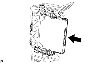
Engage the 2 claws to install the power management control ECU.
-
-
INSTALL ECU INTEGRATION BOX
-
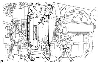
Install the ECU integration box with the bolt and 2 nuts.
- Torque:
- 5.5 N*m { 56 kgf*cm, 49 in.*lbf }
-
-
INSTALL GLOVE COMPARTMENT DOOR ASSEMBLY
Tech Tips
Use the same procedure for the RHD and LHD Click here.
-
INSTALL FRONT PASSENGER SIDE KNEE AIRBAG ASSEMBLY
Tech Tips
Use the same procedure for the RHD and LHD Click here.
-
INSTALL INSTRUMENT PANEL GARNISH LH
-
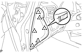
Engage the 6 clips to install the instrument panel garnish LH.
-
-
INSTALL NO. 2 INSTRUMENT PANEL UNDER COVER SUB-ASSEMBLY
Tech Tips
Use the same procedure for the RHD and LHD Click here.
-
INSTALL COWL SIDE TRIM SUB-ASSEMBLY LH
-
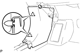
Engage the 2 clips to install the cowl side trim sub-assembly LH.
-
Install the clip.
-
-
INSTALL FRONT DOOR SCUFF PLATE LH
-
w/ Illumination:
-
Connect the connector.
-
-
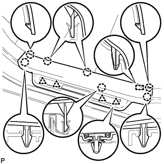
Engage the 4 clips, guide and 7 claws, and install the front door scuff plate LH.
-
-
INSTALL INSTRUMENT PANEL FINISH PANEL
-
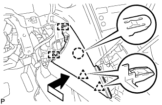
Engage the 2 guides, claw and 2 clips to install the instrument panel finish panel as shown in the illustration.
-
-
INSTALL UPPER CONSOLE PANEL SUB-ASSEMBLY
Tech Tips
Use the same procedure for the RHD and LHD Click here.
-
INSTALL SHIFT LEVER KNOB SUB-ASSEMBLY
-
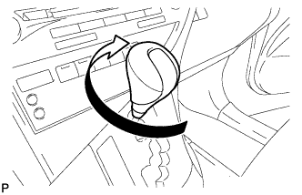
Turn the shift lever knob sub-assembly clockwise to install the shift lever knob sub-assembly.
-
-
CONNECT CABLE TO NEGATIVE BATTERY TERMINAL
Note
When disconnecting the cable, some systems need to be initialized after the cable is reconnected Click here.
-
INSPECT SRS WARNING LIGHT
-
Inspect the SRS warning light Click here.
-