CAN COMMUNICATION SYSTEM TERMINALS OF ECU

Note
-
Turn the engine switch off before measuring the resistances between CAN bus main wires and between CAN bus branch wires.
-
Turn the engine switch off before inspecting CAN bus wires for a ground short.
-
After the engine switch is turned off, check that the key reminder warning system and light reminder warning system are not operating.
-
Before measuring the resistance, leave the vehicle as is for at least 1 minute and do not operate the engine switch, any other switches or the doors. If any doors need to be opened in order to check connectors, open the doors and leave them open.
-
This section describes the standard CAN values for all CAN related components.
Tech Tips
-
Operating the engine switch, any other switches or a door triggers related ECU and sensor communication on the CAN. This communication will cause the resistance value to change.
-
Even after DTCs are cleared, if a DTC is stored again after driving the vehicle for a while, the malfunction may be occurring due to vibration of the vehicle. In such a case, wiggling the ECUs or wire harness while performing the inspection below may help determine the cause of the malfunction.
-
CAN NO. 1 JUNCTION CONNECTOR (for LHD)
-
Check the CAN No. 1 junction connector.
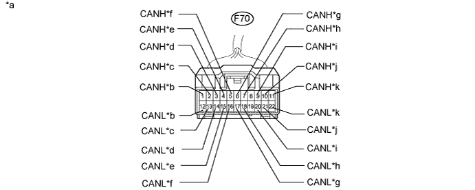
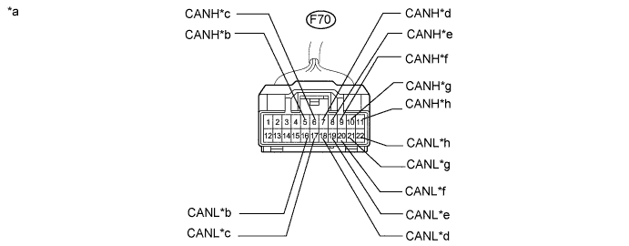
Text in Illustration *a Front view of wire harness connector (to CAN No. 1 Junction Connector) *b to Power Steering ECU *c to Steering Angle Sensor *d to DLC3 *e to Combination Meter *f to Main Body ECU *g to ECM *h to CAN No. 2 Junction Connector *i to Power Management Control ECU *j to Center Airbag Sensor Assembly *k to Yaw Rate Sensor - - -
Check the connection diagram of the components which are connected to the CAN No. 1 junction connector.
Terminal No. (Symbol) Wiring Color Connected to F70-1 (CANH) G Power steering ECU F70-12 (CANL) R F70-2 (CANH) BE Steering angle sensor F70-13 (CANL) R F70-3 (CANH) V DLC3 F70-14 (CANL) R F70-4 (CANH) P Combination meter F70-15 (CANL) R F70-5 (CANH) Y Main body ECU F70-16 (CANL) R F70-6 (CANH) GR ECM F70-17 (CANL) R F70-7 (CANH) B CAN No. 2 junction connector F70-18 (CANL) R F70-9 (CANH) LG Power management control ECU F70-20 (CANL) R F70-10 (CANH) R Center airbag sensor F70-21 (CANL) L F70-11 (CANH) BR Yaw rate sensor F70-22 (CANL) R
-
-
CAN NO. 2 JUNCTION CONNECTOR (for LHD)
-
Check the CAN No. 2 junction connector.
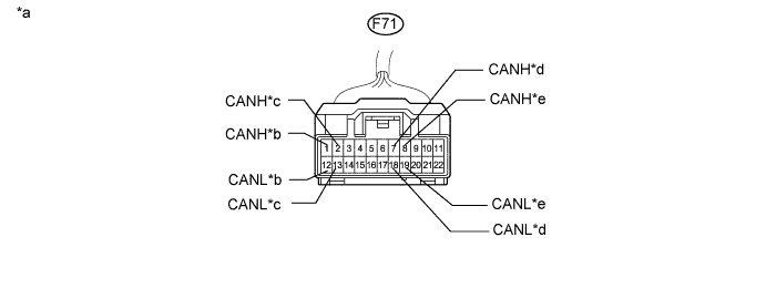
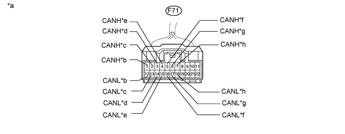
Text in Illustration *a Front view of wire harness connector (to CAN No. 2 Junction Connector) *b to Skid Control ECU *c to Certification ECU *d to CAN No. 1 Junction Connector *e
-
to Multi-media Module Receiver Assembly
-
to Radio Receiver Assembly
- - -
-
Check the connection diagram of the components which are connected to the CAN No. 2 junction connector.
Terminal No. (Symbol) Wiring Color Connected to F71-1 (CANH) GR Skid control ECU F71-12 (CANL) R F71-2 (CANH) LG Certification ECU F71-13 (CANL) R F71-7 (CANH) B CAN No. 1 junction connector F71-18 (CANL) R F71-8 (CANH) SB
-
Multi-media module receiver assembly
-
Radio receiver assembly
F71-19 (CANL) R -
-
-
CAN NO. 3 JUNCTION CONNECTOR (for LHD)
-
Check the CAN No. 3 junction connector.
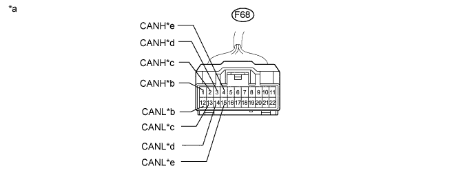
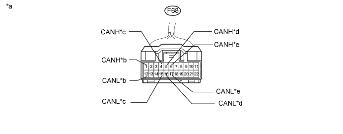
Text in Illustration *a Front view of wire harness connector (to CAN No. 3 Junction Connector) *b to Power Management Control ECU *c to Driving Support ECU Assembly *d to AFS ECU *e to CAN No. 4 Junction Connector - - -
Check the connection diagram of the components which are connected to the CAN No. 3 junction connector.
Terminal No. (Symbol) Wiring Color Connected to F68-1 (CANH) G Power management control ECU F68-12 (CANL) L F68-2 (CANH) BE Driving support ECU assembly F68-13 (CANL) L F68-3 (CANH) B AFS ECU F68-14 (CANL) L F68-4 (CANH) BR CAN No. 4 junction connector F68-15 (CANL) L
-
-
CAN NO. 4 JUNCTION CONNECTOR (for LHD)
-
Check the CAN No. 4 junction connector.
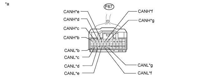
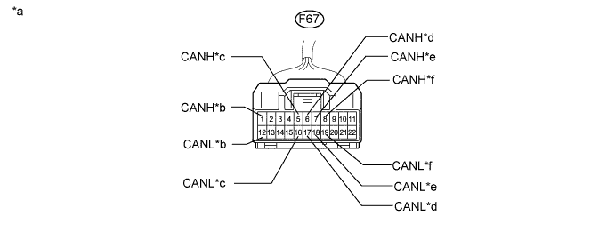
Text in Illustration *a Front view of wire harness connector (to CAN No. 4 Junction Connector) *b to 4WD Control ECU *c to Suspension Control ECU *d to Seat Belt Control ECU *e
-
to Parking Assist ECU*A
-
to Clearance Warning ECU*B
*f to CAN No. 5 Junction Connector *g to CAN No. 3 Junction Connector - - *A: w/ Parking assist monitor system (w/ side monitor system)
*B: w/ LEXUS parking assist-sensor system (w/o side monitor system)
-
-
Check the connection diagram of the components which are connected to the CAN No. 4 junction connector.
Terminal No. (Symbol) Wiring Color Connected to F67-1 (CANH) LG 4WD control ECU F67-12 (CANL) L F67-2 (CANH) P Suspension control ECU F67-13 (CANL) L F67-3 (CANH) V Seat belt control ECU F67-14 (CANL) L F67-4 (CANH) Y
-
Parking assist ECU*A
-
Clearance warning ECU*B
F67-15 (CANL) L F67-5 (CANH) GR CAN No. 5 junction connector F67-16 (CANL) L F67-6 (CANH) BR CAN No. 3 junction connector F67-17 (CANL) L *A: w/ Parking assist monitor system (w/ side monitor system)
*B: w/ LEXUS parking assist-sensor system (w/o side monitor system)
-
-
-
CAN NO. 1 JUNCTION CONNECTOR (for RHD)
-
Check the CAN No. 1 junction connector.
Text in Illustration *a Front view of wire harness connector (to CAN No. 1 Junction Connector) *b to Main Body ECU *c to ECM *d to CAN No. 2 Junction Connector *e to Multi-media Module Receiver Assembly *f to Power Management Control ECU *g to Center Airbag Sensor Assembly *h to Yaw Rate Sensor -
Check the connection diagram of the components which are connected to the CAN No. 1 junction connector.
Terminal No. (Symbol) Wiring Color Connected to F70-5 (CANH) Y Main body ECU F70-16 (CANL) R F70-6 (CANH) GR ECM F70-17 (CANL) R F70-7 (CANH) B CAN No. 2 junction connector F70-18 (CANL) R F70-8 (CANH) SB Multi-media module receiver assembly F70-19 (CANL) R F70-9 (CANH) LG Power management control ECU F70-20 (CANL) R F70-10 (CANH) R Center airbag sensor F70-21 (CANL) L F70-11 (CANH) BR Yaw rate sensor F70-22 (CANL) R
-
-
CAN NO. 2 JUNCTION CONNECTOR (for RHD)
-
Check the CAN No. 2 junction connector.
Text in Illustration *a Front view of wire harness connector (to CAN No. 2 Junction Connector) *b to Skid Control ECU *c to Certification ECU *d to DLC3 *e to Combination Meter *f to Steering Angle Sensor *g to Power Steering ECU *h to CAN No. 1 Junction Connector -
Check the connection diagram of the components which are connected to the CAN No. 2 junction connector.
Terminal No. (Symbol) Wiring Color Connected to F71-1 (CANH) GR Skid control ECU F71-12 (CANL) R F71-2 (CANH) LG Certification ECU F71-13 (CANL) R F71-3 (CANH) V DLC3 F71-14 (CANL) R F71-4 (CANH) P Combination meter F71-15 (CANL) R F71-5 (CANH) BE Steering angle sensor F71-16 (CANL) R F71-6 (CANH) G Power steering ECU F71-17 (CANL) R F71-7 (CANH) B CAN No. 1 junction connector F71-18 (CANL) R
-
-
CAN NO. 3 JUNCTION CONNECTOR (for RHD)
-
Check the CAN No. 3 junction connector.
Text in Illustration *a Front view of wire harness connector (to CAN No. 3 Junction Connector) *b to Power Management Control ECU *c to CAN No. 4 Junction Connector *d to Seat Belt Control ECU *e
-
to Parking Assist ECU*A
-
to Clearance Warning ECU*B
- - *A: w/ Parking assist monitor system (w/ side monitor system)
*B: w/ LEXUS parking assist-sensor system (w/o side monitor system)
-
-
Check the connection diagram of the components which are connected to the CAN No. 3 junction connector.
Terminal No. (Symbol) Wiring Color Connected to F68-1 (CANH) G Power management control ECU F68-12 (CANL) L F68-4 (CANH) BR CAN No. 4 junction connector F68-15 (CANL) L F68-5 (CANH) V Seat belt control ECU F68-16 (CANL) L F68-6 (CANH) Y
-
Parking assist ECU*A
-
Clearance warning ECU*B
F68-17 (CANL) L *A: w/ Parking assist monitor system (w/ side monitor system)
*B: w/ LEXUS parking assist-sensor system (w/o side monitor system)
-
-
-
CAN NO. 4 JUNCTION CONNECTOR (for RHD)
-
Check the CAN No. 4 junction connector.
Text in Illustration *a Front view of wire harness connector (to CAN No. 4 Junction Connector) *b to 4WD Control ECU *c to CAN No. 5 Junction Connector *d to CAN No. 3 Junction Connector *e to Driving Support ECU Assembly *f to AFS ECU -
Check the connection diagram of the components which are connected to the CAN No. 4 junction connector.
Terminal No. (Symbol) Wiring Color Connected to F67-1 (CANH) LG 4WD control ECU F67-12 (CANL) L F67-5 (CANH) GR CAN No. 5 junction connector F67-16 (CANL) L F67-6 (CANH) BR CAN No. 3 junction connector F67-17 (CANL) L F67-7 (CANH) BE Driving support ECU assembly F67-18 (CANL) L F67-8 (CANH) B AFS ECU F67-19 (CANL) L
-
-
CAN NO. 5 JUNCTION CONNECTOR
-
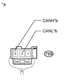
Text in Illustration *a Rear view of wire harness connector
(to CAN No. 5 Junction Connector)
*b to CAN No. 4 Junction Connector Check the CAN No. 5 junction connector.
-
Check the connection diagram of the components which are connected to the CAN No. 5 junction connector.
Terminal No. (Symbol) Wiring Color Connected to F69-3 (CANH) GR CAN No. 4 junction connector F69-2 (CANL) L
-
-
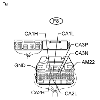
CAN NO. 6 JUNCTION CONNECTOR
-
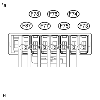
Text in Illustration *a Component with harness connected
(CAN No. 6 Junction Connector)
Check the CAN No. 6 junction connector.
-
Check the connection diagram of the components which are connected to the CAN No. 6 junction connector.
Terminal No. (Symbol) Wiring Color Connected to F73-1 (CANH) GR Outer mirror control ECU RH F73-2 (CANL) W F74-1 (CANH) BR Multiplex tilt and telescopic ECU F74-2 (CANL) W F75-1 (CANH) G Position control ECU LH F75-2 (CANL) W F76-1 (CANH) B Power back door ECU F76-2 (CANL) W F77-1 (CANH) LG Outer mirror control ECU LH F77-2 (CANL) W F78-1 (CANH) BE Main body ECU F78-2 (CANL) W F87-1 (CANH) Y Position control ECU RH F87-2 (CANL) W
-
-
CAN NO. 7 JUNCTION CONNECTOR
-
Check the CAN No. 7 junction connector.
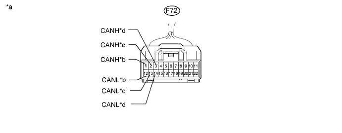
Text in Illustration *a Front view of wire harness connector (to CAN No. 7 Junction Connector) *b to Air Conditioning Amplifier *c to Power Management Control ECU *d to ECM -
Check the connection diagram of the components which are connected to the CAN No. 7 junction connector.
Terminal No. (Symbol) Wiring Color Connected to F72-1 (CANH) B Air conditioning amplifier F72-12 (CANL) W F72-2 (CANH) V Power management control ECU F72-13 (CANL) W F72-3 (CANH) G ECM F72-14 (CANL) W
-
-
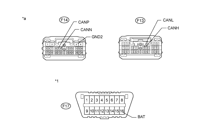
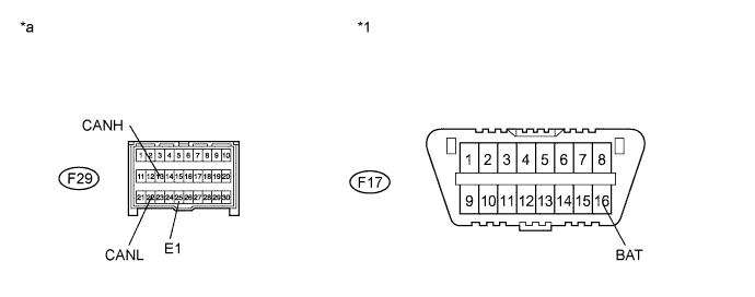
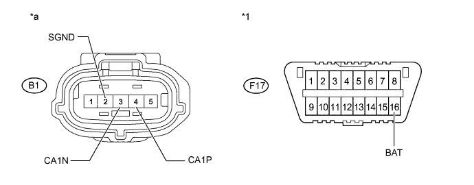
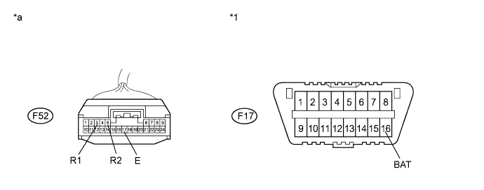
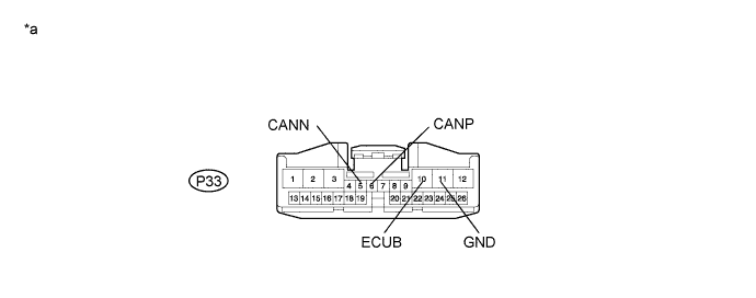
DLC3
-
Measure the resistance according to the value(s) in the table below.
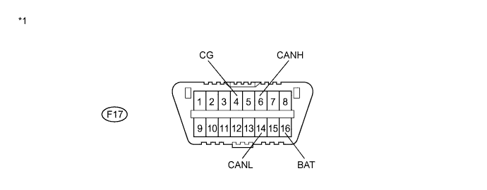
Text in Illustration *1 DLC3 - -
-
-
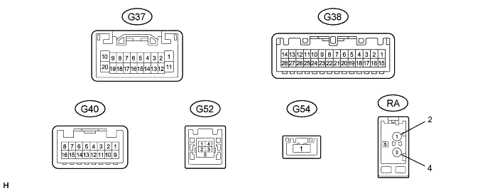
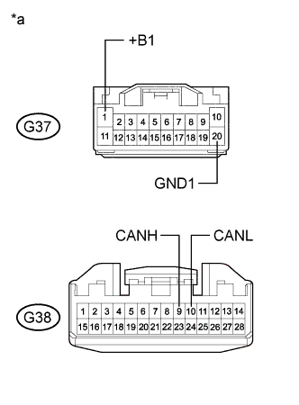
ECM (for 2GR-FE)
-
Disconnect the connectors of the ECM.
Text in Illustration *a Front view of wire harness connector (to ECM) - - -
Measure the resistance according to the value(s) in the table below.
-
-
ECM (for 1AR-FE)
-
Disconnect the connectors of the ECM.
Text in Illustration *a Front view of wire harness connector (to ECM) - - -
Measure the resistance according to the value(s) in the table below.
-
-
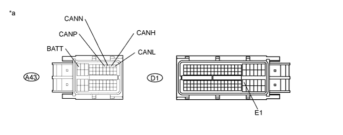
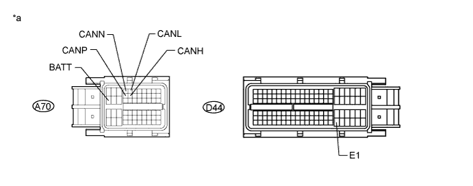
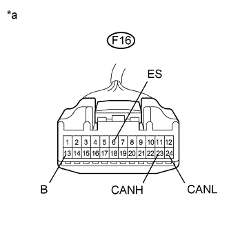
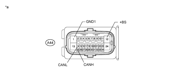
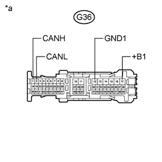
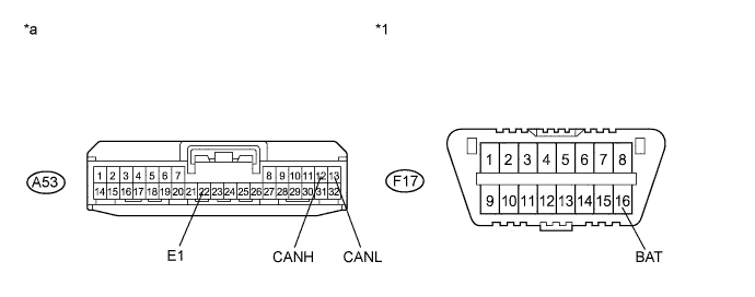
MAIN BODY ECU (MULTIPLEX NETWORK BODY ECU)
-
Disconnect the connectors of the main body ECU.
Text in Illustration *1 DLC3 - - *a Front view of wire harness connector (to Main Body ECU) - - -
Measure the resistance according to the value(s) in the table below.
-
-
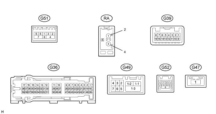
COMBINATION METER
-
Text in Illustration *a Front view of wire harness connector
(to Combination Meter)
Disconnect the connector of the combination meter.
-
Measure the resistance according to the value(s) in the table below.
-
-
POWER STEERING ECU
-
Disconnect the connectors of the power steering ECU.
Text in Illustration *a Front view of wire harness connector (to Power steering ECU) - - -
Measure the resistance according to the value(s) in the table below.
-
-
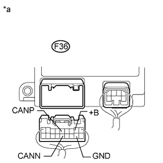
AIR CONDITIONING AMPLIFIER
-
Disconnect the connector of the air conditioning amplifier.
Text in Illustration *a Front view of wire harness connector (to Air Conditioning Amplifier) - - -
Measure the resistance according to the value(s) in the table below.
-
-
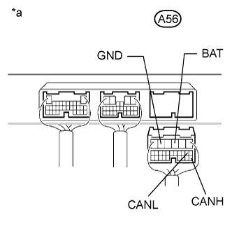
CENTER AIRBAG SENSOR ASSEMBLY
-
Disconnect the connector of the center airbag sensor assembly.
Text in Illustration *1 DLC3 - - *a Front view of wire harness connector (to Center Airbag Sensor Assembly) - - -
Measure the resistance according to the value(s) in the table below.
-
-
SKID CONTROL ECU (BRAKE ACTUATOR)
-
Disconnect the connector of the brake actuator (skid control ECU).
Text in Illustration *a Front view of wire harness connector (to Skid Control ECU) - - -
Measure the resistance according to the value(s) in the table below.
-
-
STEERING ANGLE SENSOR
-
Text in Illustration *a Front view of wire harness connector
(to Steering Angle Sensor)
Disconnect the connector of the steering angle sensor.
-
Measure the resistance according to the value(s) in the table below.
-
-
YAW RATE SENSOR
-
Text in Illustration *1 DLC3 *a Front view of wire harness connector
(to Yaw Rate Sensor)
Disconnect the connector of the yaw rate sensor.
-
Measure the resistance according to the value(s) in the table below.
-
-
CERTIFICATION ECU (SMART KEY ECU)
-
Disconnect the connector of the certification ECU.
Text in Illustration *a Front view of wire harness connector (to Certification ECU) - - -
Measure the resistance according to the value(s) in the table below.
-
-
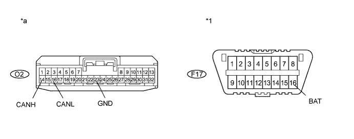
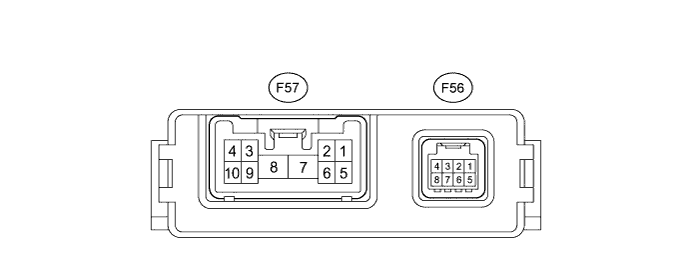
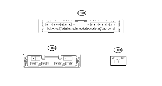
MULTI-MEDIA MODULE RECEIVER ASSEMBLY
-
Text in Illustration *a Front view of wire harness connector
(to Multi-media Module Receiver Assembly)
Disconnect the connector of the multi-media module receiver assembly.
-
Measure the resistance according to the value(s) in the table below.
-
-
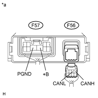
RADIO RECEIVER ASSEMBLY
-
Text in Illustration *a Front view of wire harness connector
(to Radio Receiver Assembly)
Disconnect the connectors of the radio receiver assembly.
-
Measure the resistance according to the value(s) in the table below.
-
-
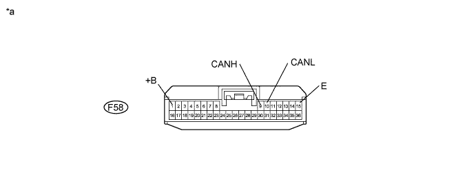
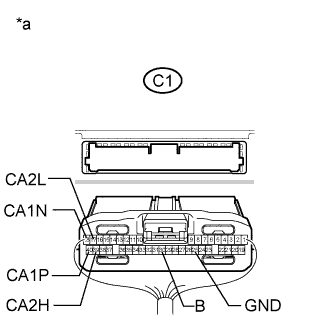
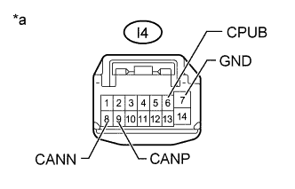
POWER MANAGEMENT CONTROL ECU
-
Text in Illustration *a Rear view of wire harness connector
(to Power Management control ECU)
Disconnect the connector of the power management control ECU.
-
Measure the resistance according to the value(s) in the table below.
-
-
AFS ECU (HEADLIGHT SWIVEL ECU)
-
Disconnect the connector of the AFS ECU.
Text in Illustration *1 DLC3 - - *a Front view of wire harness connector (to AFS ECU) - - -
Measure the resistance according to the value(s) in the table below.
-
-
4WD CONTROL ECU (for AWD)
-
Disconnect the connector of the 4WD control ECU.
Text in Illustration *1 DLC3 - - *a Front view of wire harness connector (to 4WD Control ECU) - - -
Measure the resistance according to the value(s) in the table below.
-
-
SUSPENSION CONTROL ECU
-
Text in Illustration *a Rear view of wire harness connector
(to Suspension Control ECU)
Disconnect the connector of the suspension control ECU.
-
Measure the resistance according to the value(s) in the table below.
-
-
SEAT BELT CONTROL ECU
-
Text in Illustration *a Rear view of wire harness connector
(to Seat Belt Control ECU)
Disconnect the connectors of the seat belt control ECU.
-
Measure the resistance according to the value(s) in the table below.
-
-
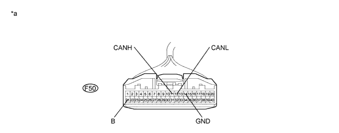
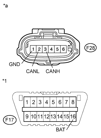
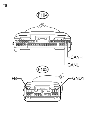
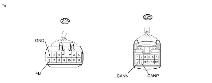
DRIVING SUPPORT ECU ASSEMBLY
-
Disconnect the connector of the driving support ECU assembly.
-
Text in Illustration *a Rear view of wire harness connector
(to Driving Support ECU Assembly)
Measure the resistance according to the value(s) in the table below.
-
-
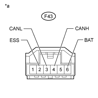
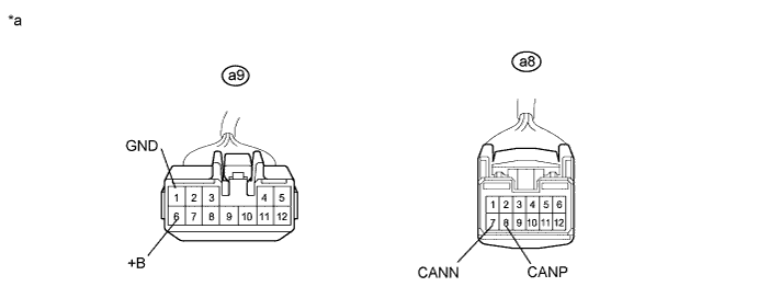
MILLIMETER WAVE RADAR SENSOR ASSEMBLY
-
Disconnect the connector of the millimeter wave radar sensor assembly.
Text in Illustration *1 DLC3 - - *a Front view of wire harness connector
(to Millimeter Wave Radar Sensor Assembly)
- - -
Measure the resistance according to the value(s) in the table below.
-
-
PARKING ASSIST ECU
-
Text in Illustration *a Front view of wire harness connector
(to Parking Assist ECU)
Disconnect the connectors of the parking assist ECU.
-
Measure the resistance according to the value(s) in the table below.
-
-
CLEARANCE WARNING ECU
-
Disconnect the connector of the clearance warning ECU.
Text in Illustration *1 DLC3 - - *a Front view of wire harness connector (to Clearance Warning ECU) - - -
Measure the resistance according to the value(s) in the table below.
-
-
TILT AND TELESCOPIC ECU (MULTIPLEX TILT AND TELESCOPIC ECU)
Text in Illustration *a Rear view of wire harness connector
(to Multiplex Tilt and Telescopic ECU)
-
Disconnect the connector of the multiplex tilt and telescopic ECU.
-
Measure the resistance according to the value(s) in the table below.
-
-
OUTER MIRROR CONTROL ECU RH
-
Text in Illustration *a Front view of wire harness connector
(to Outer Mirror Control ECU RH)
Disconnect the connector of the outer mirror control ECU RH.
-
Measure the resistance according to the value(s) in the table below.
-
-
OUTER MIRROR CONTROL ECU LH
-

Text in Illustration *a Front view of wire harness connector
(to Outer Mirror Control ECU LH)
Disconnect the connector of the outer mirror control ECU LH.
-
Measure the resistance according to the value(s) in the table below.
-
-
POSITION CONTROL ECU RH
-
Disconnect the connectors of the position control ECU RH.
Text in Illustration *a Front view of wire harness connector (to Position Control ECU RH) - - -
Measure the resistance according to the value(s) in the table below.
-
-
POSITION CONTROL ECU LH
-
Disconnect the connectors of the position control ECU LH.
Text in Illustration *a Front view of wire harness connector (to Position Control ECU LH) - - -
Measure the resistance according to the value(s) in the table below.
-
-
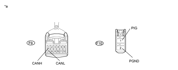
POWER BACK DOOR ECU (BACK DOOR MOTOR UNIT)
-
Disconnect the connector of the power back door ECU (back door motor unit).
Text in Illustration *a Front view of wire harness connector (to Power Back Door ECU) - - -
Measure the resistance according to the value(s) in the table below.
-