CHARGING SYSTEM, Diagnostic DTC:P1550, P1551, P1552

| DTC Code | DTC Name |
|---|---|
| P1550 | Battery Current Sensor Circuit |
| P1551 | Battery Current Sensor Circuit Low |
| P1552 | Battery Current Sensor Circuit High |
DESCRIPTION
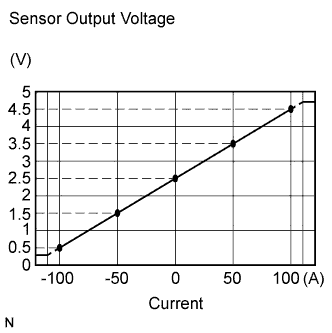
The battery current sensor assembly installed on the negative (-) battery terminal detects the amount of current supplied from the generator.
The battery current sensor assembly changes current to voltage (at the negative (-) battery terminal) and sends it to the power management ECU. The power management ECU controls the voltage of the generator based on the signals from the battery current sensor assembly.
| DTC No. | DTC Detection Condition | Trouble Area |
|---|---|---|
| P1550 | Difference between the maximum and minimum current values of the battery current sensor is 1 A or less for 10 seconds or more (1 trip detection logic) |
|
| P1551 | Battery current sensor output value is 0.2 V or less for 0.5 seconds or more with the engine switch on (IG) (1 trip detection logic) |
|
| P1552 | Battery current sensor output value is 4.8 V or more for 0.5 seconds or more with the engine switch on (IG) (1 trip detection logic) |
|
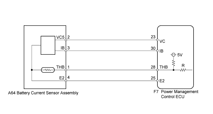
WIRING DIAGRAM
INSPECTION PROCEDURE
PROCEDURE
-
CHECK ANY OTHER DTCS OUTPUT (IN ADDITION TO P1550, P1551, P1552)
-
Connect the intelligent tester to the DLC3.
-
Turn the engine switch on (IG).
-
Turn the tester on.
-
Enter the following menus: Body / Charging Control / DTC.
-
Read the DTC.
Result Result Proceed to DTC P1550, P1551 and P1552 are output A DTC P1550, P1551, P1552 and other DTCs are output B Tech Tips
If any DTCs other than P1550, P1551, P1552 are output, troubleshoot those DTCs first.
B 
GO TO DTC CHART Click here
A 
-
-
READ VALUE USING INTELLIGENT TESTER (BATTERY CURRENT)
-
Turn all electrical systems (headlights, blower motor, rear defogger, etc.) off.
-
Enter the following menus: Body / Charging Control / Data List / Battery Current.
Result Result Proceed to Battery current is fixed at 0 A, or fluctuates by +/- 1 A or less between -98 and 98 A A Battery current fluctuates between -20 and 0 A B
B
CHECK FOR INTERMITTENT PROBLEMS
A
-
-
INSPECT BATTERY CURRENT SENSOR ASSEMBLY
-
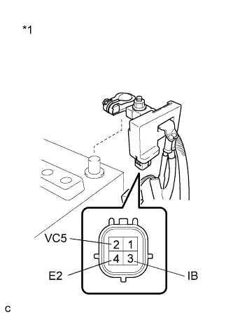
Text in Illustration *1 Component without harness connected
(Battery Current Sensor Assembly)
Disconnect the cable from the negative (-) battery terminal.
-
Disconnect the battery current sensor assembly connector.
-
Measure the resistance according to the value(s) in the table below.
Standard Resistance Tester Connection Condition Specified Condition 2 (VC5) - 4 (E2) Always 0.1 to 10 kΩ 2 (VC5) - 3 (IB) Always Below 0.5 kΩ 3 (IB) - 4 (E2) Always 0.05 to 10 kΩ -
Reconnect the cable to the negative (-) battery terminal.
NG
REPLACE BATTERY CURRENT SENSOR ASSEMBLY Click here
OK
-
-
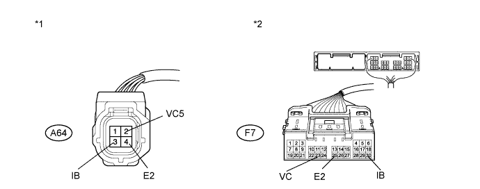
CHECK HARNESS AND CONNECTOR (BATTERY CURRENT SENSOR - POWER MANAGEMENT CONTROL ECU)
-
Disconnect the power management control ECU connector.
-
Measure the resistance according to the value(s) in the table below.
Standard Resistance (Check for Open) Tester Connection Condition Specified Condition A64-3 (IB) - F7-30 (IB) Always Below 1 Ω A64-2 (VC5) - F7-23 (VC) Always Below 1 Ω A64-4 (E2) - F7-25 (E2) Always Below 1 Ω Standard Resistance (Check for Short) Tester Connection Condition Specified Condition A64-3 (IB) or F7-30 (IB) - Body ground Always 10 kΩ or higher A64-2 (VC5) or F7-23 (VC) - Body ground Always 10 kΩ or higher A64-4 (E2) or F7-25 (E2) - Body ground Always 10 kΩ or higher Text in Illustration *1 Front view of wire harness connector
(to Battery Current Sensor Assembly)
*2 Front view of wire harness connector
(to Power Management Control ECU)
-
Reconnect the battery current sensor assembly connector.
-
Reconnect the power management control ECU connector.
NG
REPAIR OR REPLACE HARNESS OR CONNECTOR
OK 
REPLACE POWER MANAGEMENT CONTROL ECU Click here
-