- Click here
CHECK BATTERY CONDITION
Note:If the battery is weak or if the engine is difficult to start, perform the following procedure.
-
Check the battery for damage and deformation. If severe damage, deformation or leakage is found, replace the battery.
-
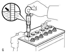
Check the electrolyte quantity of each cell.
-
For maintenance-free batteries:
-
If the electrolyte quantity is below the lower line, replace the battery.
-
If the electrolyte quantity is above the lower line, check the battery voltage when cranking the engine. If the voltage is less than 9.6 V, recharge or replace the battery.
Tip:Before checking the battery voltage, turn off all the electrical systems (headlights, blower motor, rear defogger, etc.).
-
-
For non-maintenance-free batteries:
-
If the electrolyte quantity is below the lower line, add distilled water to each cell. Then, recharge the battery and check the electrolyte specific gravity.
Standard specific gravity 1.25 to 1.29 at 20°C (68°F) If the electrolyte quantity is above the lower line, check the battery voltage when cranking the engine. If the voltage is less than 9.6 V, recharge or replace the battery.
Tip:Before checking the battery voltage, turn off all the electrical systems (headlights, blower motor, rear defogger, etc.).
-
-
-
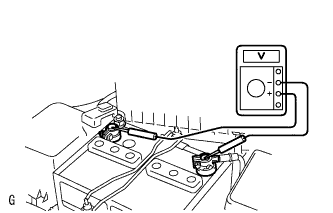
Check the voltage.
-
Turn the engine switch off and turn on the headlights for 20 to 30 seconds. This will remove the surface charge from the battery.
-
Measure the battery voltage according to the value(s) in the table below.
Standard Voltage Tester Connection Condition Specified Condition Positive (+) terminal - Negative (-) terminal 20°C (68°F) 12.6 to 12.8 V Tip:If the voltage is not as specified, charge the battery.
-
-
- Click here
CHECK BATTERY TERMINAL
-
Check that the battery terminals are not loose or corroded.
If the terminals are corroded, clean them.
-
- Click here
CHECK FUSES
-
Measure the resistance of each fuse for the charging system.
Tip:The fuses shown in the System Diagram are related to the charging system.
Standard resistance Below 1 Ω
-
If any of the results is not as specified, replace the fuse(s) as necessary.
-
-
- Click here
CHECK V-RIBBED BELT
-
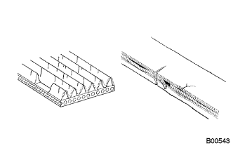
Check the belt for wear, cracks or other signs of damage.
If any of the following defects is found, replace the V-ribbed belt.
-
The belt is cracked.
-
The belt is worn out to the extent that the cords are exposed.
-
The belt has chunks missing from the ribs.
-
-
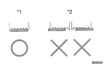
Check that the belt fits properly in the ribbed grooves.
Table 1. Text in Illustration *1 CORRECT *2 INCORRECT Tip:Check with your hand to confirm that the belt has not slipped out of the groove on the bottom of the pulley.
If it has slipped out, replace the V-ribbed belt. Install a new V-ribbed belt correctly.
-
- Click here
INSPECT GENERATOR WIRING
-
Visually check the generator wiring.
-
Check that the wiring is in good condition.
-
-
- Click here
CHECK FOR ABNORMAL NOISES
-
Listen for abnormal noises from the generator.
-
Check that no abnormal noises are heard from the generator while the engine is running.
-
-
- Click here
INSPECT CHARGE WARNING LIGHT CIRCUIT
-
Turn the engine switch on (IG). Check that the charge warning light comes on.
-
Start the engine and check that the light goes off.
If the light does not operate as specified, troubleshoot the charge warning light circuit.
-
- Click here
INSPECT CHARGING CIRCUIT WITHOUT LOAD
-
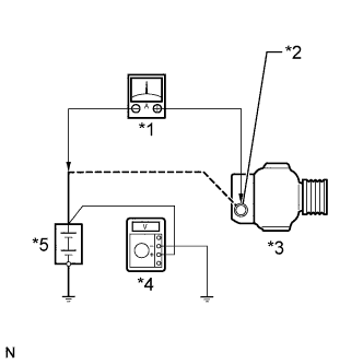
Connect a voltmeter and an ammeter to the charging circuit as follows.
Table 2. Text in Illustration *1 Ammeter *2 Terminal B *3 Battery *4 Voltmeter *5 Generator
-
Disconnect the wire from terminal B of the generator and connect it to the negative (-) lead of the ammeter.
-
Connect the ammeter positive (+) lead to terminal B of the generator.
-
Connect the voltmeter positive (+) lead to the positive (+) terminal of the battery.
-
Ground the voltmeter negative (-) lead.
-
-
Check the charging circuit.
-
Keep the engine speed at 2000 rpm and check the reading on the ammeter and voltmeter.
Standard current 10 A or less Standard voltage 13.2 to 14.8 V If the result is not as specified, repair or replace the generator.
Tip:If the battery is not fully charged, the ammeter reading will sometimes be more than the standard current.
-
-
- Click here
INSPECT CHARGING CIRCUIT WITH LOAD
-
With the engine running at 2000 rpm, turn the high beam headlights on and turn the heater blower switch to the "HI" position.
-
Check the reading on the ammeter.
Standard current 30 A or more If the ammeter reading is less than the standard current, repair or replace the generator.
Tip:If the battery is fully charged, the indication will sometimes be less than the standard current. If this is the case, add more electrical load (operate the wipers, rear window defogger, etc.) and check the reading on the ammeter again.
-
- Click here
INSPECT CHARGING CONTROL SYSTEM
-
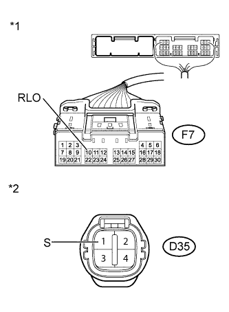
Inspect the wire harness.
Table 3. Text in Illustration *1 Front view of wire harness connector
(to Power Management Control ECU)
*2 Front view of wire harness connector
(to Generator)
-
Disconnect connector F7 of the power management control ECU.
-
Disconnect the connector of the generator assembly.
-
Measure the resistance according to the value(s) in the table below.
Standard Resistance Tester Connection Condition Specified Condition F7-10 (RLO) - D35-1 (S) Always Below 1 Ω F7-10 (RLO) or D35-1 (S) - Body ground and other terminals Always 10 kΩ or higher Tip:For the terminal arrangement of the power management control ECU, refer to terminals of ECU. (Click here)
-
-