SIDE MONITOR SYSTEM "CHK" message(s) are displayed on the SIGNAL CHECK screen.
DESCRIPTION
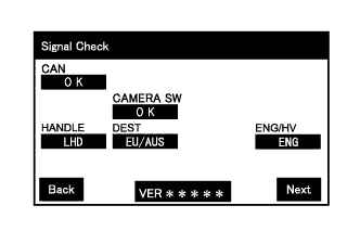
On the [Signal Check] screen, it is possible to check if the state of signals sent to the parking assist ECU is normal Click here.
Tech Tips
-
On the [Signal Check] screen, "OK" (blue) is displayed for items with a normal inspection result and input state.
-
On the [Signal Check] screen, "CHK" (red) or incorrect vehicle specification is displayed for items with an abnormal inspection result and input state.
-
Displayed items may differ depending on the specifications.
| Item | Signal Input Method | Detail | DTC Output when Abnormal Result is Displayed | Signal Output |
|---|---|---|---|---|
| CAN | CAN communication |
|
DTC is output | Brake actuator assembly (skid control ECU) |
|
Main body ECU (multiplex network body ECU) | |||
| Steering angle signal input | Spiral cable with sensor sub-assembly | |||
|
ECM | |||
| CAMERA SW | Vehicle wire harness | Side monitor main switch signal input | DTC is not output | Side monitor main switch (steering pad switch assembly) |
| HANDLE | CAN communication | Steering position signal input | DTC is output | Main body ECU (multiplex network body ECU) |
| DEST | CAN communication | Destination information signal input | DTC is output | Main body ECU (multiplex network body ECU) |
| ENG/HV | CAN communication | ENG/HV judgment signal input | DTC is output | ECM |
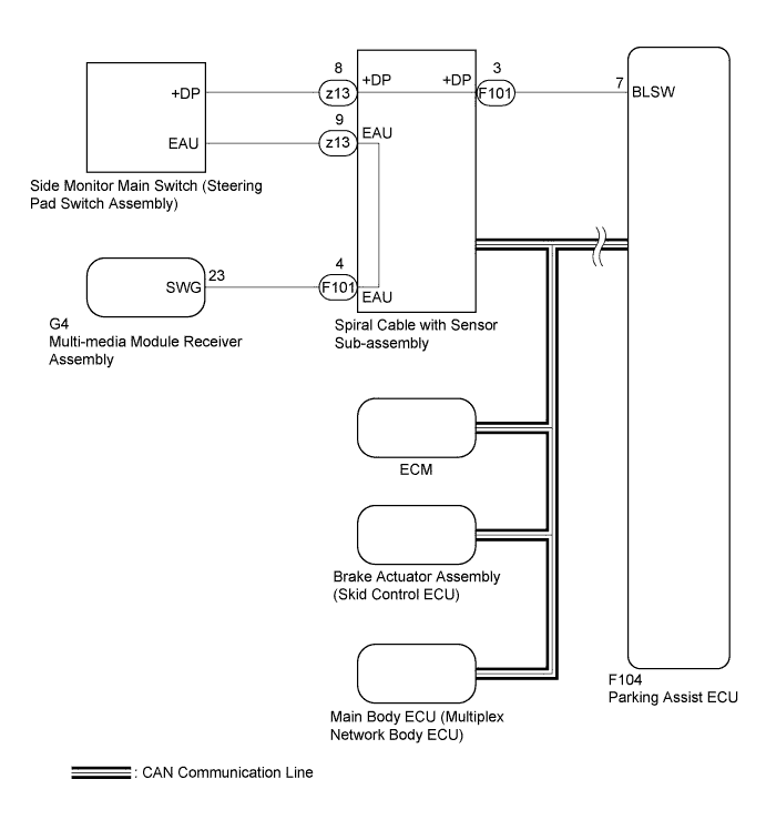
WIRING DIAGRAM
INSPECTION PROCEDURE
Note
-
When "System initializing" is displayed on the display and navigation module display after the cable is disconnected from the negative (-) battery terminal, correct the steering angle neutral point Click here.
-
Depending on the parts that are replaced or operations that are performed during vehicle inspection or maintenance, calibration of other systems as well as the side monitor system may be needed Click here.
-
Inspect the fuses for circuits related to this system before performing the following inspection procedure.
PROCEDURE
-
CHECK DISPLAY CHECK MODE
-
Check that the items on the [Signal Check] screen Click here.
Result Result Proceed to "CAMERA SW" displays "CHK" (red). A Any of "CAN", "HANDLE", "DEST" and "ENG/HV" displays "CHK" (red) or incorrect vehicle specification. B
B 
CHECK DTC OUTPUT Click here
A 
-
-
READ VALUE USING INTELLIGENT TESTER
-
Connect the intelligent tester to the DLC3.
-
Turn the engine switch on (IG).
-
Turn the intelligent tester on.
-
Enter the following menus: Chassis / Parking Assist Monitor System / Data List.
-
Read the Data List according to the display on the intelligent tester.
Parking Assist Monitor System Tester Display Measurement Item/Range Normal Condition Diagnostic Note Camera Select SW Terminal Side monitor main switch power supply voltage value/0 to 5 V Side monitor main switch on: 0 V
Side monitor main switch off: 5 V
- OK The side monitor main switch functions as specified in the normal condition column.
NG 
INSPECT SIDE MONITOR MAIN SWITCH (STEERING PAD SWITCH ASSEMBLY) Click here
OK 
REPLACE PARKING ASSIST ECU Click here
-
-
INSPECT SIDE MONITOR MAIN SWITCH (STEERING PAD SWITCH ASSEMBLY)
-
Remove the steering pad switch assembly Click here.
-
Inspect the side monitor main switch on the steering pad switch assembly Click here.
NG
REPLACE STEERING PAD SWITCH ASSEMBLY Click here
OK
-
-
INSPECT SPIRAL CABLE WITH SENSOR SUB-ASSEMBLY
-
Disconnect the z13 steering pad switch assembly connector.
-
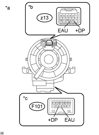
Text in Illustration *a Component without harness connected
(Spiral Cable with Sensor Sub-assembly)
*b Steering Pad Switch Assembly Side *c Vehicle Side Disconnect the F101 spiral cable with sensor sub-assembly connector.
-
After setting the spiral cable with sensor sub-assembly to the center position, rotate the spiral cable with sensor sub-assembly 2.5 times clockwise. Then while rotating the spiral cable with sensor sub-assembly 5 times counterclockwise, measure the resistance as shown in the table below.
Standard Resistance Tester Connection Condition Specified Condition z13-8 (+DP) - F101-3 (+DP) Always Below 1 Ω z13-9 (EAU) - F101-4 (EAU) Always Below 1 Ω z13-8 (+DP) - Body ground Always 10 kΩ or higher z13-9 (EAU) - Body ground Always 10 kΩ or higher Note
-
The spiral cable with sensor sub-assembly is an important part of the SRS airbag system. Incorrect removal or installation of the spiral cable with sensor sub-assembly may prevent the airbag from deploying. Refer to the pages shown in the brackets.
-
As the spiral cable with sensor sub-assembly may break, do not rotate the spiral cable with sensor sub-assembly more than the specified amount.
-
NG
REPLACE SPIRAL CABLE WITH SENSOR SUB-ASSEMBLY Click here
OK
-
-
CHECK HARNESS AND CONNECTOR
-
Disconnect the F101 spiral cable with sensor sub-assembly connector.
-
Disconnect the F104 parking assist ECU assembly connector.
-
Measure the resistance according to the value(s) in the table below.
Standard Resistance Tester Connection Switch Condition Specified Condition F104-7 (BLSW) - F101-3 (+DP) Always Below 1 Ω F101-4 (EAU) - Body ground Always Below 1 Ω F104-7 (BLSW) - Body ground Always 10 kΩ or higher F101-3 (+DP) - Body ground Always 10 kΩ or higher
NG
REPAIR OR REPLACE HARNESS OR CONNECTOR
OK
REPLACE PARKING ASSIST ECU Click here
-