SIDE MONITOR SYSTEM SYSTEM DESCRIPTION

-
GENERAL
-
This system has a side television camera assembly built into the outer rear view mirror assembly (for front passenger) to display the front passenger side views of the vehicle on the multi-display assembly.
-
This system consists of the following components:
-
Side television camera assembly
-
Parking assist ECU
-
Multi-media module receiver assembly
-
Multi-display assembly
-
Brake actuator assembly (skid control ECU assembly)
-
Spiral cable with sensor sub-assembly
-
ECM
-
Side monitor main switch (steering pad switch assembly)
-
Main body ECU (multiplex network body ECU)
-
-
This system is equipped with a self-diagnosis system, which is operated on a designated window that appears on the display panel, just as in the navigation system.
-
-
FUNCTION OF COMPONENTS
-
The parking assist ECU controls the system by using information from the following components.
Item Function Parking Assist ECU
-
Turns the side television camera assembly on or off based on parameters such as the display settings, the side monitor main switch signal, the shift position signal and the vehicle speed signal.
-
Transmits the side monitor signal to the multi-media module receiver assembly based on parameters such as the display settings, the side monitor main switch signal, the shift position signal and the vehicle speed signal.
-
Depending on the display settings, renders the output display for the side monitor and outputs them to the screen of the multi-display assembly.
-
With the video feed from the side television camera assembly showing the vehicle's front passenger side surroundings as a base, uses vehicle information such as the signal from the steering angle sensor to calculate and overlay a composite image and output this to the screen of the multi-display assembly.
-
Renders each configuration page in the diagnosis window and outputs the screen to the multi-display assembly.
-
When the outer rear view mirror retraction signal is received, terminates the side camera collimation/alignment.
-
Store the adjustment values while performing side monitor system calibration.
Multi-media Module Receiver Assembly Allows operation via the remote touch when the side monitor system calibration. Multi-display Assembly Side monitor or diagnosis screen is displayed on the display panel depend on display condition. Side television camera assembly
-
Mounted on the outer rear view mirror assembly (for front passenger) to transmit the side view of the vehicle to the parking assist ECU.
-
A color video camera that uses a Charge Coupled Device (CCD) and a wideangle lens.
Side Monitor Main Switch (Steering Pad Switch Assembly) Operating the switch sends a signal to the parking assist ECU. Main Body ECU (Multiplex Network Body ECU) Transmits outer rear view mirror retraction signal to parking assist ECU via CAN communication. Spiral Cable with Sensor Sub-assembly Transmits steering angle signal and sensor status signal to parking assist ECU via CAN communication. Brake Actuator Assembly (Skid Control ECU) Sends the inner brake information and ABS ACT information to the parking assist ECU through CAN communication. ECM Sends the shift position signal to the parking assist ECU via CAN communication. -
-
-
OPERATION EXPLANATION
-
The side monitor main switch operating signal is sent from the steering pad switch assembly to the parking assist ECU.
After receiving the side monitor main switch operation signal, the parking assist ECU switches the display signal for the multi-display assembly from the navigation system to the side monitor system.
-
-
DISPLAY CONDITIONS FOR SIDE MONITOR DISPLAY
-
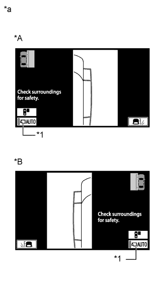
Text in Illustration *1 Automatic Mode Display Button *A for LHD *B for RHD *a Side Monitor Display Screen display operation
-
After the display conditions are met while the side monitor system is operating normally (when no DTCs are output), the side monitor display will be displayed when in both manual and automatic display mode.
Tech Tips
On the side monitor display, the display mode is as indicated below according to the operation of the automatic mode display button.
Automatic mode display button
(Indicator in the button)
Display mode On
(Illuminated)
Automatic display mode Off
(Not illuminated)
Manual display mode
-
-
Display conditions for manual display mode
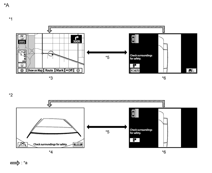
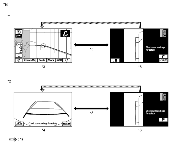
Text in Illustration *A for LHD *B for RHD *1 Shift lever in a position other than R *2 Shift lever in R *3 Navigation display etc. *4 Parking assist monitor display *5 Side monitor main switch on *6 Side monitor display *a When the vehicle speed is more than 12 km/h (7.5 mph) - -
-
The side monitor system changes the displayed image when the side monitor main switch is operated while the following conditions are met and either the engine switch is on (IG) or the engine is running (no DTCs output).
Automatic mode display button Multi Display Screen Shift Lever Position Vehicle Speed Screen
(changes due to side monitor main switch operation)
Off Navigation display etc. Other than R 12 km/h (7.5 mph) or less Navigation display etc. → Side monitor display Off Parking assist monitor display R 12 km/h (7.5 mph) or less Parking assist monitor display → Side monitor display*1 Tech Tips
*1: In this case, the side monitor display is in path line deletion mode.
-
-
Display conditions for automatic display mode
-
In automatic display mode, the side monitor system automatically changes the displayed image depending on the vehicle conditions while the following conditions are met and the system is operating normally (no DTCs output).
Vehicle Condition Multi-display Screen Shift Position Vehicle Speed Screen Stopped → Driving Navigation display etc. Except in P or R 12 km/h (7.5 mph) or less Navigation display etc. → Side monitor display*1 Driving → Stopped Navigation display etc. Except in R 10 km/h (6.2 mph) or less Navigation display etc. → Side monitor display*1
-
*1: Screen changes and screen transition conditions after the screen is automatically changed are the same as those for manual display mode (shift lever in a position other than R).
-
-
-
-
SIDE MONITOR DISPLAY MODE SETTING
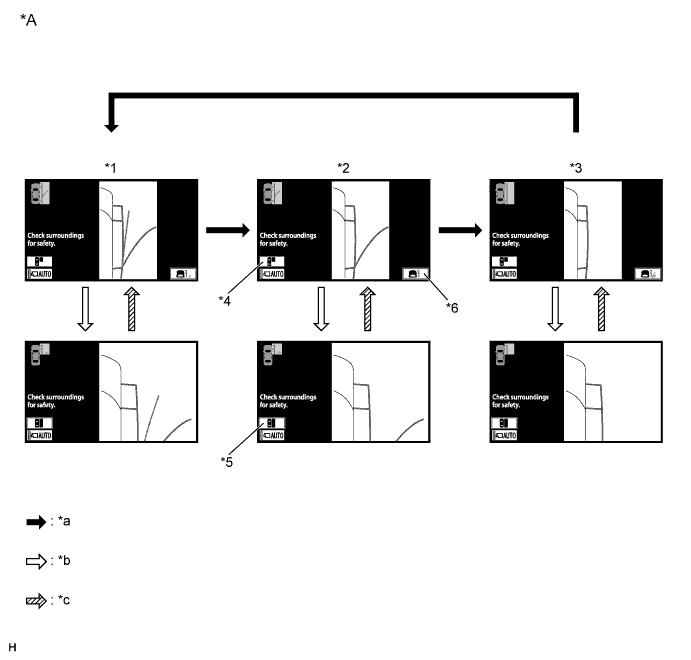
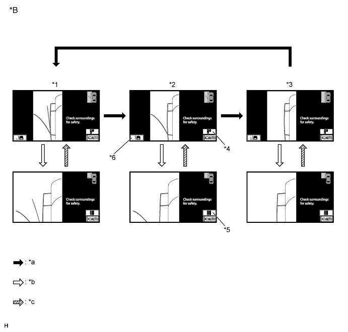
Text in Illustration *A for LHD *B for RHD *1 Predicted Minimum Turning Path Line + Predicted Path Line Mode *2 Predicted Minimum Turning Path Line Mode *3 Path line deletion mode *4 Display range button (for forward view) *5 Display range button (for overall side view) *6 Line mode button *a Line mode button on *b Display range button (for forward view) on *c Display range button (for overall side view) on - -
-
The side monitor system switches display modes when the side monitor display is displayed and the line mode button is operated. In each display mode, when the display range button (for forward view) is operated, the forward view is displayed on the screen.
Tech Tips
-
When the forward view is displayed, the display mode cannot be switched on the side monitor display.
-
When the side monitor display is displayed with the shift lever in R, the side monitor display will change to path line deletion mode.
Side Monitor Display Mode Side Monitor Display Mode Vehicle Width Parallel Line
(Blue)
Predicted Minimum Turning Path Line
(Blue)
Predicted Path Line
(Yellow)
Predicted Minimum Turning Path Line + Predicted Path Line Mode Displayed Displayed Displayed Predicted Minimum Turning Path Line Mode Displayed Displayed Not displayed Path Line Deletion Mode Displayed Not displayed Not displayed -
-
-
COMMUNICATION SYSTEM OUTLINE
-
The components of the side monitor system communicate with each other through the AVC-LAN. If a short circuit or open circuit occurs in the AVC-LAN, communication is interrupted and the side monitor system will stop functioning.
-
-
DIAGNOSTIC FUNCTION OUTLINE
-
This side monitor system has a diagnostic function displayed in the parking assist ECU. This function enables the calibration (adjustment and confirmation) of the system Click here.
-
The system can check the following items by using the intelligent tester.
Item Proceed to DTC Data List / Active Test
-