REAR VIEW MONITOR SYSTEM (except Inner Rear View Mirror Type) Image from Camera for Rear View Monitor is Abnormal
DESCRIPTION
-
The video signal of the rear television camera assembly is transmitted to the multi-display assembly via the radio receiver assembly. The radio receiver assembly transmits video signals through transmits the digital communication cable.
WIRING DIAGRAM

INSPECTION PROCEDURE
PROCEDURE
-
CHECK HARNESS AND CONNECTOR (RADIO RECEIVER ASSEMBLY - REAR TELEVISION CAMERA ASSEMBLY)
-
Disconnect the G40 radio receiver assembly connector.
-
Disconnect the Y14 rear television camera assembly connector.
-
Measure the resistance according to the value(s) in the table below.
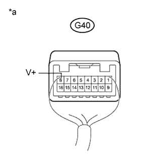
Standard Resistance Tester Connection Condition Specified Condition G40-8 (V+) - Y14-2 (CV+) Always Below 1 Ω G40-7 (CA+) - Y14-4 (CB+) Always Below 1 Ω G40-16 (V-) - Y14-1 (CV-) Always Below 1 Ω G40-8 (V+) - Body ground Always 10 kΩ or higher G40-7 (CA+) - Body ground Always 10 kΩ or higher G40-16 (V-) - Body ground Always 10 kΩ or higher G40-15 (CGND) - Body ground Always 10 kΩ or higher
NG 
REPAIR OR REPLACE HARNESS OR CONNECTOR
OK 
-
-
CHECK RADIO RECEIVER ASSEMBLY
-
Reconnect the G40 radio receiver assembly connector.
-
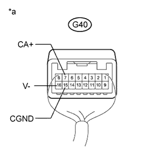
Text in Illustration *a Component with harness connected
(Radio Receiver Assembly)
Measure the resistance according to the value(s) in the table below.
Standard Resistance Tester Connection Condition Specified Condition G40-16 (V-) - Body ground Always Below 1 Ω G40-15 (CGND) - Body ground Always Below 1 Ω -
Measure the voltage according to the value(s) in the table below.
Standard Voltage Tester Connection Condition Specified Condition G40-7 (CA+) - G40-15 (CGND) Within 60 seconds of turning the engine switch on (ACC) 5.5 to 7.05 V
NG
REPLACE RADIO RECEIVER ASSEMBLY Click here
OK
-
-
CHECK REAR TELEVISION CAMERA ASSEMBLY
-
Reconnect the Y14 rear television camera assembly connector.
-
Text in Illustration *a Component with harness connected
(Radio Receiver Assembly)
Text in Illustration *a Component with harness connected
(Radio Receiver Assembly)
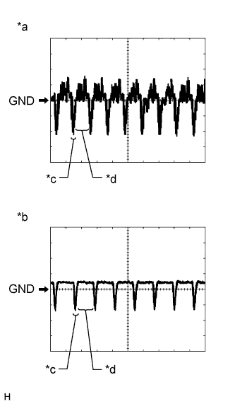
Text in Illustration *a Waveform 1 (camera lens not covered, displaying an image) *b Waveform 2 (camera lens covered, blacking out the screen) *c Synchronized Signal *d Video Waveform Check the waveform of the rear television camera assembly using an oscilloscope.
Tech Tips
A waterproof connector is used for the rear television camera assembly. Therefore, inspect the waveform at the display and navigation module display with the connector connected.
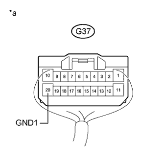
OK Waveform is as shown in the illustration. Item Content Terminal No. (Symbol) G40-8 (V+) - G37-20 (GND1) Tool Setting 200 mV/DIV., 50 μsec./DIV. Condition Engine switch on (IG), shift lever in R Tech Tips
The video waveform changes according to the image sent by the rear television camera assembly.
NG
REPLACE REAR TELEVISION CAMERA ASSEMBLY Click here
OK
-
-
REPLACE HARNESS AND CONNECTOR (RADIO RECEIVER ASSEMBLY - MULTI-DISPLAY ASSEMBLY)
-
Replace the harness and connector (radio receiver assembly - multi-display assembly).
-
Check if the same malfunction recurs when the rear view monitor screen is displayed.
Result Result Proceed to Malfunction does not recur
(returns to normal)
A Malfunction recurs B
B 
REPLACE MULTI-DISPLAY ASSEMBLY Click here
A 
END
-
-
REPLACE MULTI-DISPLAY ASSEMBLY
-
Replace the multi-display assembly with a new or known good one Click here.
-
Check if the same malfunction recurs when the rear view monitor screen is displayed.
Result Result Proceed to Malfunction does not recur
(returns to normal)
A Malfunction recurs B
B
PROCEED TO NEXT SUSPECTED AREA SHOWN IN PROBLEM SYMPTOMS TABLE Click here
A
END
-