G-BOOK SYSTEM (w/ Telematics Transceiver) Telematics Transceiver Malfunction
INSPECTION PROCEDURE
Tech Tips
When replacing the multi-media module receiver assembly or telematics transceiver, perform the vehicle contract setting Click here.
PROCEDURE
-
CHECK COMMUNICATION SERVICE CONDITION
-
Move the vehicle.
-
If the vehicle is outside the communication service area, move the vehicle to a communication service area, wait for a while and perform the operation again.
-
NEXT 
-
-
CHECK DTC
-
Clear the DTCs Click here.
-
Recheck for DTCs and check that no DTCs are output.
Result Result Proceed to DTCs are output A No DTCs are output B
B 
DCM CHECK Click here
A 
GO TO DTC DIAGNOSTIC TROUBLE CODE CHART Click here
-
-
DCM CHECK
-
DCM Check
-
Enter diagnostic mode Click here.
-
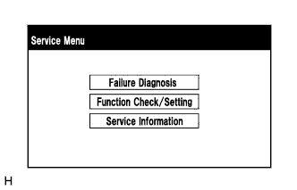
Select "Failure Diagnosis" on the "Service Menu" screen.
-
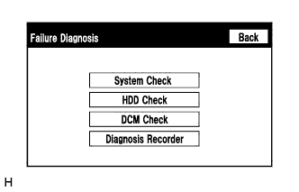
Select "DCM Check" on the "Failure Diagnosis" screen.
-
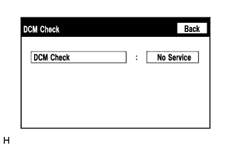
Touch "DCM Check" to perform the DCM Check.
Result Result Proceed to
-
DCM Check cannot be performed
-
The result of DCM check does not change from "wait"
-
"OK" is displayed for the result of DCM Check
-
"TIME OUT" is displayed for the result of DCM Check
A "No Service" is displayed for the result of DCM Check B "OFF LINE" is displayed for the result of DCM Check C "NO CARRIER" is displayed for the result of DCM Check D "ERROR" is displayed for the result of DCM Check E "RESTRICTION" is displayed for the result of DCM Check *a Tech Tips
-
If the vehicle is moved while the screen is displayed, select "Back" again to renew the result.
-
*a: Retry after waiting for 10 to 30 minutes.
-
-
B 
MOVE VEHICLE
C
CHECK CONTRACT FLAG Click here
D
CONTACT G-BOOK SUPPORT CENTER
E
REPLACE TELEMATICS TRANSCEIVER Click here
A
-
-
CONTACT G-BOOK SUPPORT CENTER
-
Check the contract flag.
-
Enter diagnostic mode Click here.
-
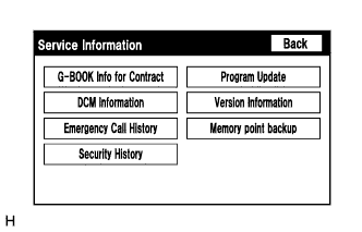
Select "Service Information" on the "Service Menu" screen.
-
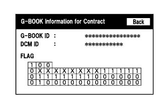
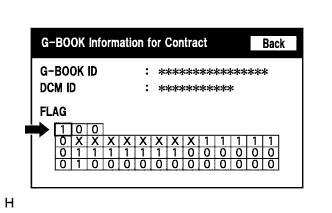
Select "G-BOOK Info for Contract" on the "Service Information" screen.
-
Check the flag information item.
-
-
Check the device information.
-
Select "DCM Information" on the "Service Information" screen.
-
Check the following items on the DCM Information screen.
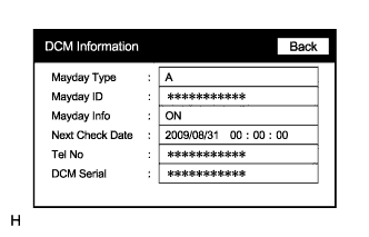
Item Content Tel No Check if the DCM phone number is displayed. If the number is displayed, record it. DCM Serial Record the DCM serial number.
-
-
Contact the G-BOOK support center.
-
Contact the G-BOOK support center and inform them about the following:
-
Phenomenon: Communication has been initialized but communication is not possible.
-
Flag information
-
Telephone number (Tel No): Not displayed / Displayed number
-
Serial number (DCM Serial): Displayed number
-
VIN
Tech Tips
The G-BOOK support center will perform an investigation and provide the results.
-
-
Check for problem symptoms after receiving a call from the G-BOOK support center.
Result Result Proceed to Problem symptom recurs A System returns to normal B
-
B
END
A
-
-
INSPECT MULTI-MEDIA MODULE RECEIVER ASSEMBLY (USBV, USBG)
-
Disconnect the G49 multi-media module receiver assembly connector.
-
Measure the resistance according to the value(s) in the table below.
Standard Resistance Tester Connection Condition Specified Condition G49-2 (USBG) - Body ground Always Below 1 Ω -
Measure the voltage according to the value(s) in the table below.
Standard Voltage Tester Connection Condition Specified Condition G49-4 (USBV) - G49-2 (USBG) Engine switch on (ACC) 4.75 to 5.25 V
NG
REPLACE MULTI-MEDIA MODULE RECEIVER ASSEMBLY Click here
OK
-
-
CHECK HARNESS AND CONNECTOR (MULTI-MEDIA MODULE RECEIVER ASSEMBLY - TELEMATICS TRANSCEIVER)
-
Check the installation condition.
-
Check the USB communication cable (digital communication cable) between the multi-media module receiver assembly and the telematics transceiver for any installation or connection problems.
-
-
Disconnect the G49 multi-media module receiver assembly connector.
-
Disconnect the G53 telematics transceiver connector.
-
Measure the resistance according to the value(s) in the table below.
Standard Resistance Tester Connection Condition Specified Condition G49-4 (USBV) - G53-4 (USBV) Always Below 1 Ω G49-2 (USBG) - G53-2 (USBG) Always Below 1 Ω G53-4 (USBV) - Body ground Always 10 kΩ or higher G53-2 (USBG) - Body ground Always 10 kΩ or higher Standard Resistance (USB Cable) Tester Connection Condition Specified Condition G49-1-2 (USB+) - G53-1-2 (USB+) Always Below 1 Ω G49-1-1 (USB-) - G53-1-1 (USB-) Always Below 1 Ω G49-1-3 (USBS) - G53-1-3 (USBS) Always Below 1 Ω G53-1-2 (USB+) - Body ground Always 10 kΩ or higher G53-1-1 (USB-) - Body ground Always 10 kΩ or higher G53-1-3 (USBS) - Body ground Always 10 kΩ or higher
NG
REPAIR OR REPLACE HARNESS OR CONNECTOR
OK
-
-
CHECK RECEPTION LEVEL
-
Check the reception level.
-
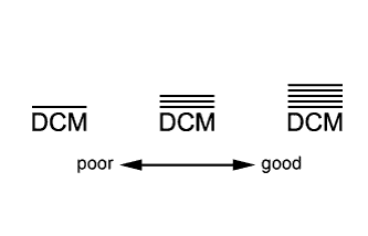
Check the reception level of the DCM.
Tech Tips
-
Check if the reception level is significantly lower by comparing it to a China Telecom cellular phone.
-
If there is no China Telecom cellular phone available, move the vehicle to a location where the reception level indicator shows 3 bars or more.
-
If a problem occurred because the G-BOOK contract has not been completed, proceed to the contract procedure and check the DCM reception level on the screen during the contract procedure.
Result Result Proceed to
-
The reception level is not lower than a China Telecom cellular phone.
-
3 or more bars are displayed for the reception level.
A
-
The reception level is lower than a China Telecom cellular phone.
-
Cannot reach 3 or more bars for the reception level even after moving the vehicle.
B -
-
B
INSPECT TELEPHONE ANTENNA ASSEMBLY Click here
A
-
-
REPLACE TELEMATICS TRANSCEIVER
-
Replace the telematics transceiver with a known good one and check if the same problem occurs again Click here.
OK The system returns to normal.
NG
REPLACE MULTI-MEDIA MODULE RECEIVER ASSEMBLY Click here
OK
END (TELEMATICS TRANSCEIVER WAS DEFECTIVE)
-
-
INSPECT TELEPHONE ANTENNA ASSEMBLY
-
Check the installation condition.
-
Check the telephone antenna assembly for any installation problems.
OK The telephone antenna assembly is installed correctly.
-
-
Disconnect the telephone antenna assembly connector.
-
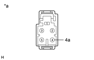
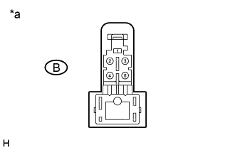
Text in Illustration *a Component without harness connected
(Telephone Antenna Assembly)
Measure the resistance according to the value(s) in the table below.
Standard Resistance Tester Connection Condition Specified Condition 4 - 4a Always 4 to 11 kΩ
NG
REPLACE TELEPHONE ANTENNA ASSEMBLY Click here
OK
-
-
INSPECT NO. 4 ANTENNA CORD SUB-ASSEMBLY
-
Disconnect the B No. 4 antenna cord sub-assembly connector from the telephone antenna assembly.
-
Disconnect the C No. 4 antenna cord sub-assembly connector from the No. 5 antenna cord sub-assembly.
-
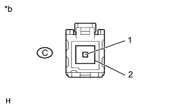
Measure the resistance according to the value(s) in the table below.
Standard Resistance Tester Connection Condition Specified Condition B-4 - C-1 Always Below 1 Ω B-4 - Body ground Always 10 kΩ or higher Text in Illustration *a Front view of No. 4 antenna cord sub-assembly connector
(to Telephone Antenna Assembly)
*b Front view of No. 4 antenna cord sub-assembly connector
(to No. 5 Antenna Cord Sub-assembly)
NG
REPLACE NO. 4 ANTENNA CORD SUB-ASSEMBLY Click here
OK
-
-
INSPECT NO. 5 ANTENNA CORD SUB-ASSEMBLY
-
Disconnect the D No. 5 antenna cord sub-assembly connector from the No. 4 antenna cord sub-assembly.
-
Disconnect the E No. 5 antenna cord sub-assembly connector from the vehicle side wire harness.
-
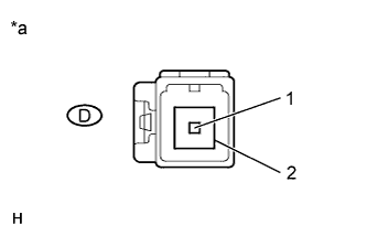
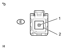
Measure the resistance according to the value(s) in the table below.
Standard Resistance Tester Connection Condition Specified Condition D-1 - E-1 Always Below 1 Ω D-1 - Body ground Always 10 kΩ or higher Text in Illustration *a Front view of No. 5 antenna cord sub-assembly connector
(to No. 4 Antenna Cord Sub-assembly)
*b Front view of No. 5 antenna cord sub-assembly connector
(to Vehicle Side Wire Harness)
NG
REPLACE NO. 5 ANTENNA CORD SUB-ASSEMBLY Click here
OK
-
-
CHECK HARNESS AND CONNECTOR (NO. 5 ANTENNA CORD SUB-ASSEMBLY - TELEMATICS TRANSCEIVER)
-
Disconnect the F vehicle side wire harness connector from the No. 5 antenna cord sub-assembly.
-
Disconnect the G telematics transceiver connector.
-
Measure the resistance according to the value(s) in the table below.
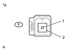
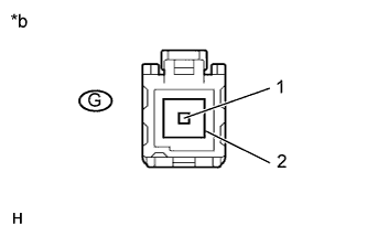
Standard Resistance Tester Connection Condition Specified Condition F-1 - G-1 Always Below 1 Ω F-1 - Body ground Always 10 kΩ or higher Text in Illustration *a Front view of wire harness connector
(to No. 5 Antenna Cord Sub-assembly)
*b Front view of wire harness connector
(to Telematics Transceiver)
NG
REPAIR OR REPLACE HARNESS OR CONNECTOR
OK
-
-
REPLACE TELEMATICS TRANSCEIVER
-
Replace the telematics transceiver with a known good one and check if the same problem occurs again Click here.
OK Same problem does not occur.
NG
REPLACE MULTI-MEDIA MODULE RECEIVER ASSEMBLY Click here
OK
END (TELEMATICS TRANSCEIVER WAS DEFECTIVE)
-
-
CHECK CONTRACT FLAG
-
Check the contract flag.
-
Enter diagnostic mode Click here.
-
Select "Service Information" on the "Service Menu" screen.
-
Select "G-BOOK Info for Contract" on the "Service Information" screen.
-
Check if the flag information shown in the illustration indicates "1".
-
Turn the engine switch off and then to on (ACC).
-
Check again if the flag information shown in the illustration indicates "1".
-
-
Recheck the problem symptom.
-
Select G-BOOK.com and perform the contract procedure again.
-
Check for the problem symptom.
Result Result Proceed to Contract flag indicates "1" and the system returns to normal. A Contract flag indicates "1" but the problem symptom recurs. B Contract flag does not indicate "1" and the problem symptom recurs. C
-
B
REPLACE TELEMATICS TRANSCEIVER Click here
C
CONTACT G-BOOK SUPPORT CENTER
A
END
-
-
CHECK PROBLEM SYMPTOM (IG OFF to ACC)
-
Check for the problem symptom.
-
Turn the engine switch off and then to on (ACC).
-
Check if the problem symptom recurs.
Result Result Proceed to System returns to normal. A System does not return to normal. B
-
B
REPLACE TELEMATICS TRANSCEIVER Click here
A
END
-