NAVIGATION RECEIVER INSTALLATION

-
PRECAUTION
Note
When installing the hard disk drive, eliminate static electricity by touching the vehicle body to prevent components from being damaged.
-
INSTALL MULTI-MEDIA MODULE RECEIVER ASSEMBLY
-
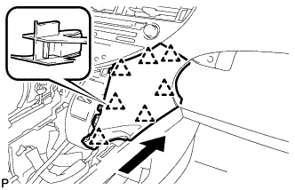
INSTALL HARD DISK DRIVE
-

Insert the hard disk drive in the direction shown by the arrow in the illustration to install it.
-
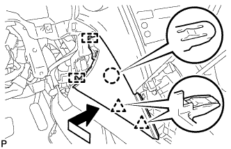
Engage the 2 guides to temporarily install the cover.
-
Install the cover with the 2 screws.
-
Install the No. 2 radio bracket with the 3 screws.
-
-
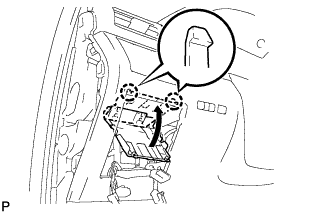
INSTALL NO. 4 INSTRUMENT PANEL REGISTER ASSEMBLY
-
Engage the 5 claws to install the No. 4 instrument panel register assembly.
-
-
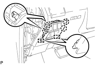
INSTALL NO. 3 INSTRUMENT PANEL REGISTER ASSEMBLY
-
Engage the 5 claws to install the No. 3 instrument panel register assembly.
-
-
INSTALL HAZARD WARNING SIGNAL SWITCH ASSEMBLY (for LHD)
-
Engage the 2 claws and install the hazard warning signal switch assembly.
-
Engage the clamp.
-
-
INSTALL HAZARD WARNING SIGNAL SWITCH ASSEMBLY (for RHD)
-
w/o Navigation System:
-
Engage the 2 claws and install the hazard warning signal switch assembly.
-
Engage the 2 clamps.
-
-
w/ Navigation System:
-
Engage the 2 claws and install the hazard warning signal switch assembly.
-
Engage the clamp.
-
-
-
INSTALL MULTI-MEDIA MODULE RECEIVER ASSEMBLY WITH REGISTER
-
Connect each connector.
-
Engage the 7 clips.
-
Install the multi-media module receiver assembly with register with the 4 bolts.
- Torque:
- 4.9 N*m { 50 kgf*cm, 43 in.*lbf }
-
-
INSTALL LOWER INSTRUMENT PANEL FINISH PANEL
-
Engage the 7 clips to install the lower instrument panel finish panel as shown in the illustration.
-
-
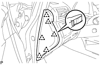
INSTALL INSTRUMENT PANEL FINISH PANEL
-
Engage the 2 guides, claw and 2 clips to install the instrument panel finish panel as shown in the illustration.
-
-
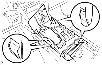
INSTALL LOWER INSTRUMENT PANEL FINISH PANEL SUB-ASSEMBLY
-
Connect each connector.
-
Engage the 8 clips and 2 guides.
-
Install the lower instrument panel finish panel sub-assembly with the 2 screws <D>.
-
Engage the 2 claws to close the cover as shown in the illustration.
-
-
INSTALL NO. 1 SWITCH HOLE BASE
-
Connect each connector.
-
Engage the 4 claws and 2 guides to install the No. 1 switch hole base.
-
-
INSTALL INSTRUMENT PANEL GARNISH LH
-
Engage the 6 clips to install the instrument panel garnish LH.
-
-
INSTALL UPPER CONSOLE PANEL SUB-ASSEMBLY
-
Engage the clamp.
-
Connect each connector.
-
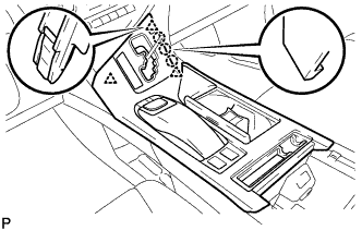
Engage the 3 claws and 3 clips.
-
w/o Seat Heater System:
-
Connect the connector to the console box hole cover.
-
-
w/ Seat Heater System:
-
Connect the connector.
-
Engage the 6 claws to install the seat heater switch with console box hole cover.
-
-
Engage the 4 claws and 4 clips to install the upper console panel sub-assembly.
-
-
INSTALL SHIFT LEVER KNOB SUB-ASSEMBLY
-
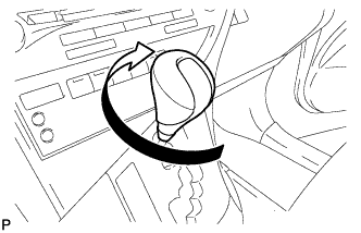
Turn the shift lever knob sub-assembly clockwise to install the shift lever knob sub-assembly.
-
-
CONNECT CABLE TO NEGATIVE BATTERY TERMINAL
CAUTION:
When disconnecting the cable, some systems need to be initialized after the cable is reconnected Click here.
-
INSPECT SUSPENSION CONTROL SYSTEM (w/ Air Suspension)
-
INSPECT HARD DISK DRIVE
-
REPLACED OPERATION
for Parking Assist Monitor System without Side Monitor: Click here
for Parking Assist Monitor System with Side Monitor: Click here
for G-BOOK System without Telematics Transceiver: Click here
for G-BOOK System with Telematics Transceiver: Click here