G-BOOK SYSTEM (w/ Telematics Transceiver), Diagnostic DTC:B15CB

| DTC Code | DTC Name |
|---|---|
| B15CB | Telematics Transceiver Antenna Disconnected |
DESCRIPTION
If an open circuit in the telephone antenna assembly is detected continuously for 1 minute as a result of a terminal check performed by the telematics transceiver every minute after the engine switch is turned on (ACC), this DTC will be stored.
| DTC No. | DTC Detection Condition | Trouble Area |
|---|---|---|
| B15CB | DCM antenna is not connected or has an open circuit. |
|
INSPECTION PROCEDURE
Tech Tips
When replacing the multi-media module receiver assembly or telematics transceiver, perform the vehicle contract setting Click here.
PROCEDURE
-
CLEAR DTC
-
Clear the DTCs Click here.
NEXT 
-
-
CHECK DTC
-
Recheck for DTCs and check that no DTCs are output Click here.
OK No DTCs are output.
NG 
INSPECT TELEPHONE ANTENNA ASSEMBLY Click here
OK 
END
-
-
INSPECT TELEPHONE ANTENNA ASSEMBLY
-
Check the installation condition.
-
Check the telephone antenna assembly for any installation problems.
OK The telephone antenna assembly is installed correctly.
-
-
Disconnect the telephone antenna assembly connector.
-
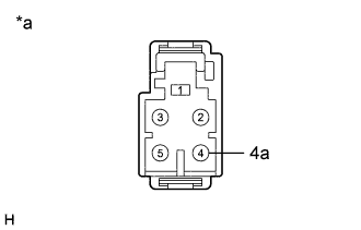
Text in Illustration *a Component without harness connected
(Telephone Antenna Assembly)
Measure the resistance according to the value(s) in the table below.
Standard Resistance Tester Connection Condition Specified Condition 4 - 4a Always 4 to 11 kΩ
NG 
REPLACE TELEPHONE ANTENNA ASSEMBLY Click here
OK
-
-
INSPECT NO. 4 ANTENNA CORD SUB-ASSEMBLY
-
Disconnect the B No. 4 antenna cord sub-assembly connector from the telephone antenna assembly.
-
Disconnect the C No. 4 antenna cord sub-assembly connector from the No. 5 antenna cord sub-assembly.
-
Measure the resistance according to the value(s) in the table below.
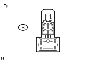
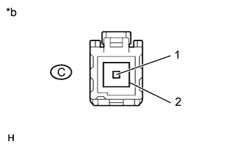
Standard Resistance Tester Connection Condition Specified Condition B-4 - C-1 Always Below 1 Ω B-4 - Body ground Always 10 kΩ or higher Text in Illustration *a Front view of No. 4 antenna cord sub-assembly connector
(to Telephone Antenna Assembly)
*b Front view of No. 4 antenna cord sub-assembly connector
(to No. 5 Antenna Cord Sub-assembly)
NG
REPLACE NO. 4 ANTENNA CORD SUB-ASSEMBLY Click here
OK
-
-
INSPECT NO. 5 ANTENNA CORD SUB-ASSEMBLY
-
Disconnect the D No. 5 antenna cord sub-assembly connector from the No. 4 antenna cord sub-assembly.
-
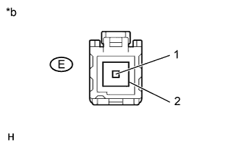
Disconnect the E No. 5 antenna cord sub-assembly connector from the vehicle side wire harness.
-
Measure the resistance according to the value(s) in the table below.
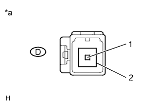
Standard Resistance Tester Connection Condition Specified Condition D-1 - E-1 Always Below 1 Ω D-1 - Body ground Always 10 kΩ or higher Text in Illustration *a Front view of No. 5 antenna cord sub-assembly connector
(to No. 4 Antenna Cord Sub-assembly)
*b Front view of No. 5 antenna cord sub-assembly connector
(to Vehicle Side Wire Harness)
NG
REPLACE NO. 5 ANTENNA CORD SUB-ASSEMBLY Click here
OK
-
-
CHECK HARNESS AND CONNECTOR (NO. 5 ANTENNA CORD SUB-ASSEMBLY - TELEMATICS TRANSCEIVER)
-
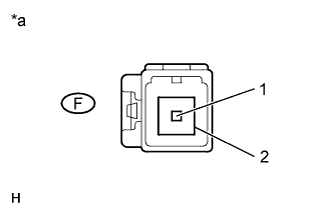
Disconnect the F vehicle side wire harness connector from the No. 5 antenna cord sub-assembly.
-
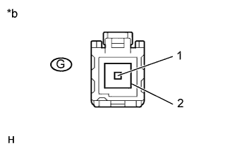
Disconnect the G telematics transceiver connector.
-
Measure the resistance according to the value(s) in the table below.
Standard Resistance Tester Connection Condition Specified Condition F-1 - G-1 Always Below 1 Ω F-1 - Body ground Always 10 kΩ or higher Text in Illustration *a Front view of wire harness connector
(to No. 5 Antenna Cord Sub-assembly)
*b Front view of wire harness connector
(to Telematics Transceiver)
NG
REPAIR OR REPLACE HARNESS OR CONNECTOR
OK
-
-
RECHECK DTC
-
Clear the DTCs Click here.
-
Recheck for DTCs and check that no DTCs are output.
OK No DTCs are output.
NG
REPLACE TELEMATICS TRANSCEIVER Click here
OK
END
-
-
REPLACE TELEMATICS TRANSCEIVER
-
Replace the telematics transceiver with a known good one and check if the same problem occurs again Click here.
NEXT
-
-
RECHECK DTC
-
Recheck for DTCs and check that no DTCs are output Click here.
OK No DTCs are output.
NG
REPLACE MULTI-MEDIA MODULE RECEIVER ASSEMBLY Click here
OK
END (TELEMATICS TRANSCEIVER WAS DEFECTIVE)
-