NAVIGATION SYSTEM, Diagnostic DTC:B1321, B1323

| DTC Code | DTC Name |
|---|---|
| B1321 | Lost Communication with EMV |
| B1323 | Lost Communication with Haptic Device |
DESCRIPTION
These DTCs are stored when communication between the multi-media module receiver assembly and remote touch is not possible.
| DTC No. | DTC Detection Condition | Trouble Area |
|---|---|---|
| B1321 | The multi-media module receiver assembly cannot receive data from remote touch. |
|
| B1323 | The remote touch cannot receive data from multi-media module receiver assembly. |
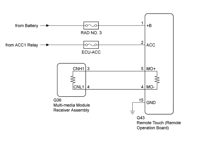
WIRING DIAGRAM
INSPECTION PROCEDURE
Note
Inspect the fuses for circuits related to this system before performing the following inspection procedure.
-
When replacing the multi-media module receiver assembly or telematics transceiver, perform vehicle contract setting (w/ Telematics Transceiver) Click here.
-
When replacing the multi-media module receiver assembly, perform vehicle contract setting (w/o Telematics Transceiver) Click here.
w/ G-BOOK System:
PROCEDURE
-
CHECK HARNESS AND CONNECTOR (MULTI-MEDIA MODULE RECEIVER ASSEMBLY - REMOTE TOUCH (REMOTE OPEARATION BOARD) )
-
Disconnect the G36 multi-media module receiver assembly connector.
-
Disconnect the G43 remote touch (remote operation board) connector.
-
Measure the resistance according to the value(s) in the table below.
Standard Resistance Tester Connection Condition Specified Condition G36-3 (CNH1) - G43-5 (MO+) Always Below 1 Ω G36-4 (CNL1) - G43-4 (MO-) Always Below 1 Ω G36-3 (CNH1) - Body ground Always Below 1 Ω G36-4 (CNL1) - Body ground Always Below 1 Ω
NG 
REPAIR OR REPLACE HARNESS OR CONNECTOR
OK 
-
-
CHECK HARNESS AND CONNECTOR (REMOTE TOUCH (REMOTE OPERATION BOARD) POWER SOURCE)
-
Disconnect the G43 remote touch (remote operation board) connector.
-
Measure the voltage according to the value(s) in the table below.
Standard Voltage Tester Connection Condition Specified Condition G43-1 (+B) - Body ground Always 11 to 14 V G43-2 (ACC) - Body ground Engine switch on (ACC) 11 to 14 V -
Measure the resistance according to the value(s) in the table below.
Standard Resistance Tester Connection Condition Specified Condition G43-15 (GND) - Body ground Always Below 1 Ω
NG
REPAIR OR REPLACE HARNESS OR CONNECTOR
OK
-
-
REMOTE TOUCH SELF CHECK (REMOTE TOUCH SWITCH KNOB FEEDBACK FORCE GENERATION CHECK)
-
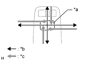
Text in Illustration *a Switch Knob *b Control Direction *c Feedback Force Check the remote touch switch knob feedback force.
-
Move the remote touch switch knob up, down, right and left to check that feedback force is generated.
OK Feedback force is generated. Tech Tips
When the engine switch is turned on (ACC), feedback force is generated. When the engine switch is turned off, feedback force is not generated, and the remote touch switch knob will move freely.
-
NG
REPLACE REMOTE OPERATION BOARD Click here
OK
-
-
REPLACE MULTI-MEDIA MODULE RECEIVER ASSEMBLY
-
Replace the multi-media module receiver assembly Click here.
-
Check if the same malfunction recurs.
Result Result Proceed to Malfunction does not recur
(returns to normal)
A Malfunction recurs B
B
REPLACE REMOTE OPERATION BOARD Click here
A 
END
-