RADIO RECEIVER REMOVAL

-
REMOVE SHIFT LEVER KNOB SUB-ASSEMBLY
-
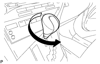
Turn the shift lever knob sub-assembly counterclockwise and remove the shift lever knob sub-assembly.
-
-
REMOVE UPPER CONSOLE PANEL SUB-ASSEMBLY
-
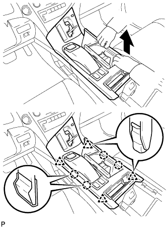
Move the shift lever to N.
-
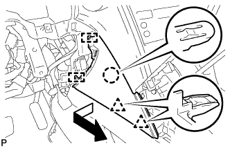
Pull the upper console panel sub-assembly in the direction indicated by the arrow to disengage the 4 claws and 4 clips.
-
w/o Seat Heater System:
-
Disconnect the connector from the console box hole cover.
-
-
w/ Seat Heater System:
-
Disengage the 6 claws.
-
Disconnect the connector and remove the seat heater switch with console box hole cover.
-
-
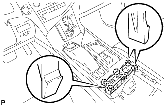
Pull the upper console panel sub-assembly in the direction indicated by the arrow to disengage the 3 claws and 3 clips.
-
Disconnect each connector.
-
Disengage the clamp and remove the upper console panel sub-assembly.
-
-
REMOVE INSTRUMENT PANEL GARNISH LH
-
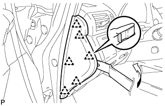
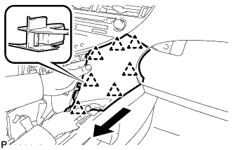
Using moulding remover B, disengage the 6 clips and remove the instrument panel garnish LH as shown in the illustration.
-
-
REMOVE NO. 1 SWITCH HOLE BASE
-
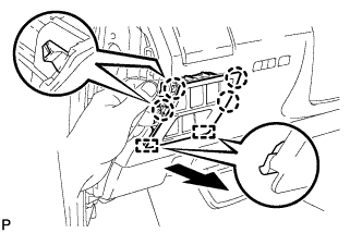
Push the No. 1 switch hole base in the direction indicated by the arrow to disengage the 4 claws and 2 guides.
-
Disconnect each connector and remove the No. 1 switch hole base.
-
-
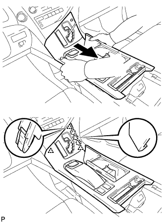
REMOVE LOWER INSTRUMENT PANEL FINISH PANEL SUB-ASSEMBLY
-
Disengage the 2 claws and open the cover as shown in the illustration.
-
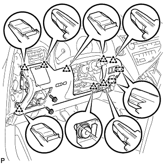
Remove the 2 screws <D>.
-
Disengage the 8 clips and 2 guides.
-
Disconnect each connector and remove the lower instrument panel finish panel sub-assembly.
-
-
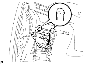
REMOVE INSTRUMENT PANEL FINISH PANEL
-
Pull the instrument panel finish panel in the direction indicated by the arrow to disengage the claw, 2 clips and 2 guides, and remove the instrument panel finish panel.
-
-
REMOVE LOWER INSTRUMENT PANEL FINISH PANEL
-
Pull the lower instrument panel finish panel in the direction indicated by the arrow to disengage the 7 clips and remove the lower instrument panel finish panel.
-
-
REMOVE RADIO RECEIVER ASSEMBLY WITH REGISTER
Note
-
The 4 bolts of the radio receiver assembly with register are installed though the service holes at the bottom in the instrument panel. Make sure to check all of them.
-
If the radio receiver assembly with register is pulled without removing the 4 bolts, it may result in damage to the radio receiver assembly with register.
-
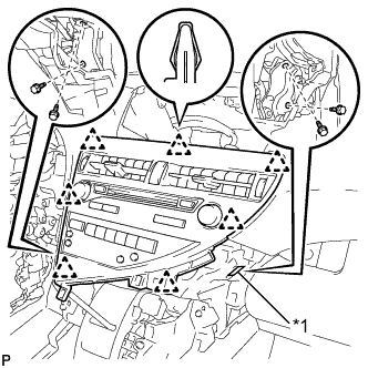
Text in Illustration *1 Service Hole Remove the 4 bolts.
-
Disengage the 7 clips.
-
Disconnect each connector and remove the radio receiver assembly with register.
-
-
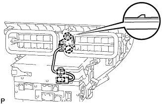
REMOVE HAZARD WARNING SIGNAL SWITCH ASSEMBLY (for LHD)
-
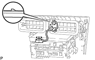
Disengage the clamp.
-
Using a screwdriver, disengage the 2 claws and remove the hazard warning signal switch assembly.
-
-
REMOVE HAZARD WARNING SIGNAL SWITCH ASSEMBLY (for RHD)
-
w/o Navigation System:
-
Disengage the 2 clamps.
-
Using a screwdriver, disengage the 2 claws and remove the hazard warning signal switch assembly.
-
-
w/ Navigation System:
-
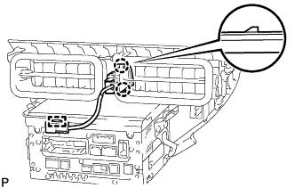
Disengage the clamp.
-
Using a screwdriver, disengage the 2 claws and remove the hazard warning signal switch assembly.
-
-
-
REMOVE NO. 3 INSTRUMENT PANEL REGISTER ASSEMBLY
-
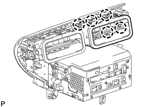
Disengage the 5 claws and remove the No. 3 instrument panel register assembly.
-
-
REMOVE NO. 4 INSTRUMENT PANEL REGISTER ASSEMBLY
-
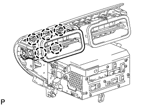
Disengage the 5 claws and remove the No. 4 instrument panel register assembly.
-
-
REMOVE RADIO RECEIVER ASSEMBLY