STEREO COMPONENT AMPLIFIER REMOVAL

-
PRECAUTION
Note
After turning the engine switch off, waiting time may be required before disconnecting the cable from the negative (-) battery terminal. Therefore, make sure to read the disconnecting the cable from the negative (-) battery terminal notices before proceeding with work Click here.
-
DISCONNECT CABLE FROM NEGATIVE BATTERY TERMINAL
CAUTION:
Wait at least 90 seconds after disconnecting the cable from the battery negative (-) terminal to disable the SRS system.
Note
When disconnecting the cable, some systems need to be initialized after the cable is reconnected Click here.
-
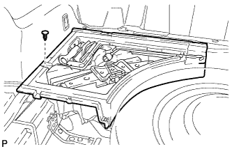
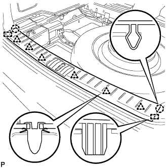
REMOVE DECK BOARD SUB-ASSEMBLY
-
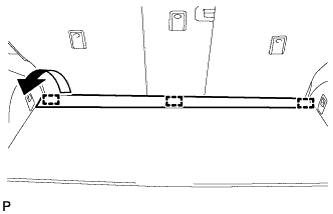
Disengage the 3 fasteners as shown in the illustration.
-
for Compact Spare Tire:
-
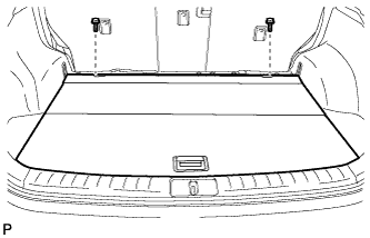
Remove the 2 bolts and remove the deck board sub-assembly.
-
-
for Full Size Spare Tire:
-
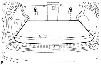
Remove the 2 bolts and remove the deck board sub-assembly.
-
-
-
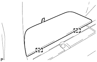
REMOVE SPARE WHEEL COVER ASSEMBLY (for Compact Spare Tire)
-
Remove the spare wheel cover assembly.
-
-
REMOVE NO. 4 REAR FLOOR BOARD (for Compact Spare Tire)
-
Disengage the 2 guides and remove the No. 4 rear floor board.
-
-
REMOVE NO. 4 REAR FLOOR BOARD (for Full Size Spare Tire)
-
Disengage the 2 guides and remove the No. 4 rear floor board.
-
-
REMOVE NO. 3 REAR FLOOR BOARD (for Compact Spare Tire)
-
Disengage the 2 guides and remove the No. 3 rear floor board.
-
-
REMOVE NO. 3 REAR FLOOR BOARD (for Full Size Spare Tire)
-
Disengage the 2 guides and remove the No. 3 rear floor board.
-
-
REMOVE TONNEAU COVER ASSEMBLY
-
Remove the tonneau cover assembly.
-
-
REMOVE REAR DECK FLOOR BOX
-
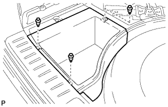
Remove the 3 clips and the rear deck floor box.
-
-
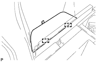
REMOVE DECK SIDE TRIM BOX LH (for Compact Spare Tire)
-
Remove the 2 clips and the deck side trim box LH.
-
-
REMOVE DECK SIDE TRIM BOX LH (for Full Size Spare Tire)
-
Remove the 3 clips and the deck side trim box LH.
-
-
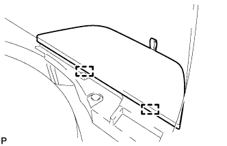
REMOVE DECK SIDE TRIM BOX RH (for Compact Spare Tire)
-
Remove the 2 clips and deck side trim box RH.
-
-
REMOVE DECK SIDE TRIM BOX RH (for Full Size Spare Tire)
-
Remove the 3 clips and the deck side trim box RH.
-
-
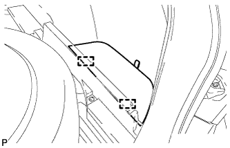
REMOVE FRONT DECK FLOOR BOX
-
Remove the clip and the front deck floor box.
-
-
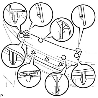
REMOVE REAR FLOOR FINISH PLATE
-
Disengage the 2 claws, 6 clips and 2 guides, and remove the rear floor finish plate.
-
-
REMOVE REAR FLOOR FINISH SIDE PLATE LH
-
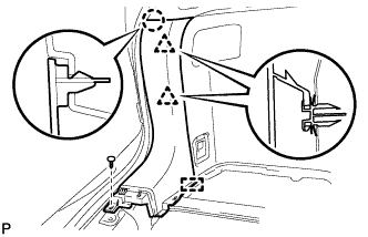
Remove the clip.
-
Disengage the claw and 2 clips.
-
Disengage the guide and remove the rear floor finish side plate LH.
-
-
REMOVE REAR SEAT ASSEMBLY LH
Tech Tips
Refer to the procedure up to Remove Rear Seat Assembly Click here.
-
REMOVE REAR DOOR SCUFF PLATE LH
-
Disengage the 6 claws, 3 clips and guide, and remove the rear door scuff plate LH.
-
-
REMOVE REAR SEAT SIDE COVER LH
-
Remove the 2 clips.
-
Disengage the 2 claws and 3 clips, and remove the rear seat side cover LH.
Tech Tips
A part of the clip remains on the vehicle side.
-
-
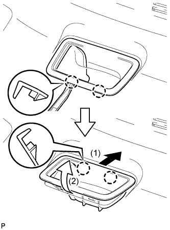
REMOVE NO. 1 LUGGAGE COMPARTMENT TRIM HOOK (for LH Side)
-
Remove the No. 1 luggage compartment trim hook as shown in the illustration.
-
-
REMOVE ROPE HOOK ASSEMBLY (for LH Side)
-
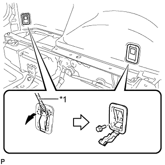
Text in Illustration *1 Protective Tape Using a screwdriver, disengage the 2 claws.
Tech Tips
Tape the screwdriver tip before use.
-
Remove the 2 bolts and the 2 rope hook assemblies.
-
-
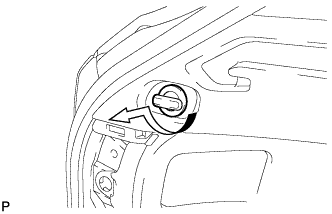
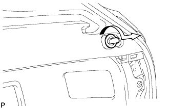
REMOVE RECLINING REMOTE CONTROL BEZEL LH
-
Using moulding remover A, disengage the 2 bottom claws of the reclining remote control bezel LH.
-
Lift the reclining remote control bezel LH as shown by the arrow (1) in the illustration.
-
Turn the reclining remote control bezel LH as shown by the arrow (2) in the illustration, then disengage the 2 upper claws and remove the bezel.
-
-
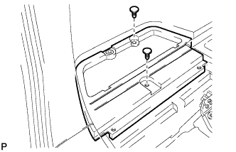
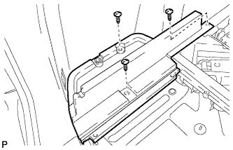
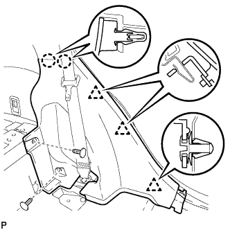
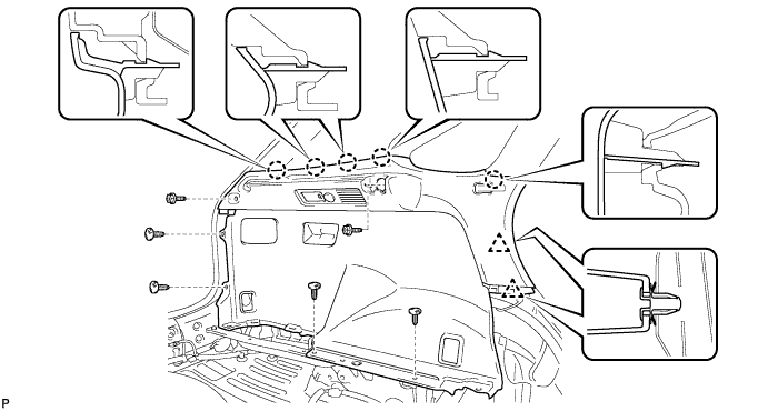
REMOVE DECK TRIM SIDE PANEL ASSEMBLY LH
-
Remove the 2 screws.
-
Remove the 4 clips.
-
Disengage the 5 claws and 2 clips.
-
Disconnect each connector and remove the deck trim side panel assembly LH.
-
-
REMOVE REAR FLOOR FINISH SIDE PLATE RH
Tech Tips
Use the same procedure for the RH side and the LH side.
-
REMOVE REAR SEAT ASSEMBLY RH
Tech Tips
Refer to the procedure up to Remove Rear Seat Assembly Click here.
-
REMOVE REAR DOOR SCUFF PLATE RH
Tech Tips
Use the same procedure for the RH side and the LH side.
-
REMOVE REAR SEAT SIDE COVER RH
Tech Tips
Use the same procedure for the RH side and the LH side.
-
REMOVE NO. 1 LUGGAGE COMPARTMENT TRIM HOOK (for RH Side)
-
Remove the No. 1 luggage compartment trim hook as shown in the illustration.
-
-
REMOVE ROPE HOOK ASSEMBLY (for RH Side)
Tech Tips
Use the same procedure for the RH side and the LH side.
-
REMOVE RECLINING REMOTE CONTROL BEZEL RH
Tech Tips
Use the same procedure for the RH side and the LH side.
-
REMOVE HEIGHT CONTROL SWITCH (w/ Air Suspension)
-
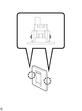
Disengage the 2 claws to remove the height control switch from the deck trim side panel assembly RH.
-
Disconnect the connector.
-
-
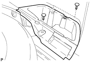
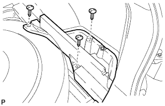
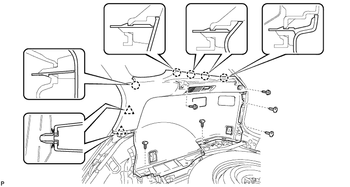
REMOVE DECK TRIM SIDE PANEL ASSEMBLY RH
-
Remove the 2 screws.
-
Remove the 5 clips.
-
Disengage the 5 claws and 2 clips.
-
Disconnect the connector and remove the deck trim side panel assembly RH.
-
-
REMOVE NO. 1 DECK BOARD REINFORCEMENT
-
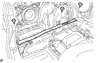
Remove the 3 bolts and No. 1 deck board reinforcement.
-
-
REMOVE NO. 2 DECK BOARD REINFORCEMENT
-
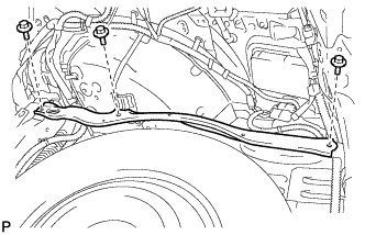
Remove the 3 bolts and No. 2 deck board reinforcement.
-
-
REMOVE REAR SEAT SUB FLOOR PANEL ASSEMBLY
-
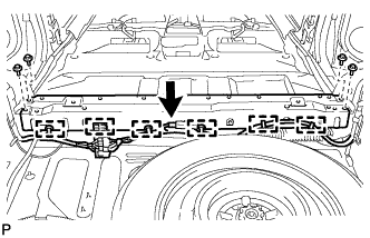
Disconnect the connector.
-
Disengage the 6 clamps and disconnect the wire harness.
-
Remove the 4 bolts and rear seat sub floor panel assembly.
-
-
REMOVE STEREO COMPONENT AMPLIFIER ASSEMBLY WITH BRACKET
-
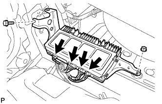
Disconnect the 4 connectors.
-
Remove the bolt, nut and stereo component amplifier assembly with bracket.
-
-
REMOVE NO. 2 AMPLIFIER BRACKET
-
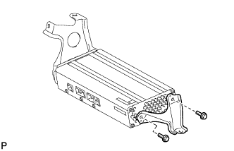
Remove the 2 bolts and No. 2 amplifier bracket.
-
-
REMOVE NO. 1 AMPLIFIER BRACKET
-
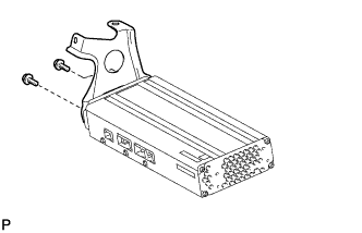
Remove the 2 bolts and No. 1 amplifier bracket.
-