STEERING COLUMN ASSEMBLY REMOVAL

CAUTION:
Some of these service operations affect the SRS airbag system. Read the precautionary notices concerning the SRS airbag system before servicing Click here.
Note
-
Do not replace the spiral cable with the battery connected and the engine switch on (IG).
-
Do not rotate the spiral cable without the steering wheel with the battery connected and the engine switch on (IG).
-
Ensure that the steering wheel is installed and aligned straight when inspecting the steering sensor.
-
Do not remove the steering sensor from the spiral cable.
-
PRECAUTION (w/ Navigation System for HDD)
Note
After the engine switch is turned off, the display and navigation module display (HDD navigation system) records various types of memory and settings. As a result, after turning the engine switch off, make sure to wait for the time specified in the following table before disconnecting the cable from the negative (-) battery terminal.
Waiting Time before Disconnecting Cable from Negative (-) Battery Terminal Specification Waiting Time w/o Telematics transceiver 60 sec. w/ Telematics transceiver 120 sec. -
PRECAUTION (w/ Air Suspension)
Note
Be sure to read Precaution thoroughly before servicing Click here.
-
PRECAUTION
Note
Be sure to read Precaution thoroughly before servicing Click here.
-
ALIGN FRONT WHEELS FACING STRAIGHT AHEAD
-
DISCONNECT CABLE FROM NEGATIVE BATTERY TERMINAL
-
Disable the auto away / return function by changing the customize parameter Click here.
Note
Record the current customize parameter setting (whether the auto tilt away function is enabled or disabled) in order to restore the current setting after finishing this operation.
Tech Tips
Performing the above operation disables the auto away / return function when the engine switch is turned off.
-
Turn the engine switch on (IG). Operate the tilt and telescopic switch to fully extend and lower the steering column assembly.
-
Turn the engine switch off and disconnect the cable from the negative (-) battery terminal.
CAUTION:
Wait at least 90 seconds after disconnecting the cable from the negative (-) battery terminal to disable the SRS system.
Note
When disconnecting the cable, some systems need to be initialized after the cable is reconnected Click here.
-
-
REMOVE FRONT WHEEL LH
-
REMOVE STEERING PAD
Tech Tips
Refer to the instructions for Removal of the steering pad Click here.
-
REMOVE STEERING WHEEL ASSEMBLY
-
Disconnect each connector from the spiral cable.
-
w/ Steering Heater:
-
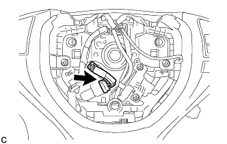
Disconnect the connector.
-
-
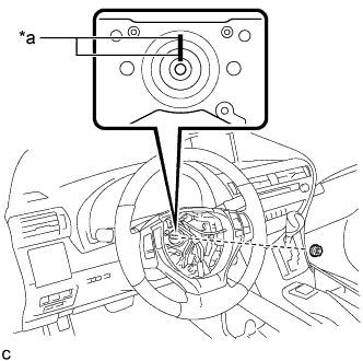
Text in Illustration *a Matchmark Remove the steering wheel assembly set nut.
-
Put matchmarks on the steering wheel assembly and steering main shaft.
-
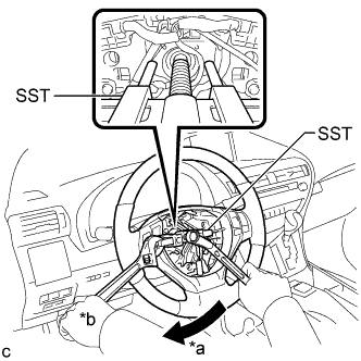
Text in Illustration *a Turn *b Hold Using SST, remove the steering wheel assembly.
- SST
- 09950-50013 ( 09951-05010, 09952-05010, 09953-05020, 09954-05070 )
Note
Apply a small amount of grease to the threads and tip of SST (09953-05020) before use.
-
-
REMOVE BRAKE PEDAL SUPPORT ASSEMBLY (for LHD)
Tech Tips
Refer to the instructions for Removal of the brake pedal Click here.
-
REMOVE BRAKE PEDAL SUPPORT ASSEMBLY (for RHD)
Tech Tips
Refer to the instructions for Removal of the brake pedal Click here.
-
REMOVE STEERING COLUMN COVER
Note
Removing the lower steering column cover in the incorrect order will cause the parts to break.
-
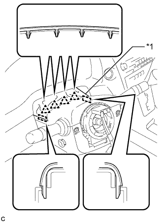
Text in Illustration *1 Instrument Panel Cluster Finish Panel Disengage the 4 clips and 2 guides to separate the instrument panel cluster finish panel from the upper steering column cover.
-
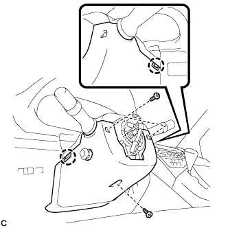
Remove the 3 screws.
-
Disengage the 2 claws to remove the lower steering column cover.
Note
Do not damage the tilt and telescopic switch.
-
Disengage the claw to remove the upper steering column cover.
-
-
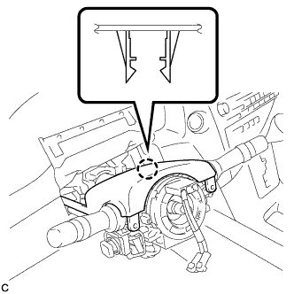
REMOVE TURN SIGNAL SWITCH ASSEMBLY WITH SPIRAL CABLE SUB-ASSEMBLY
-
Disconnect the connectors from the turn signal switch assembly with spiral cable sub-assembly.
-
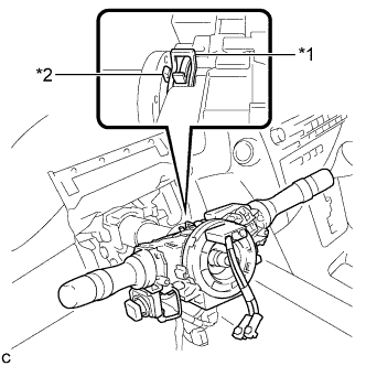
Text in Illustration *1 Clamp *2 Claw Using pliers, expand the clamp.
-
While holding the clamp expanded, raise the claw using a screwdriver to disengage it, and then remove the turn signal switch assembly with spiral cable sub-assembly from the steering column assembly.
-
-
SEPARATE STEERING INTERMEDIATE SHAFT ASSEMBLY
-
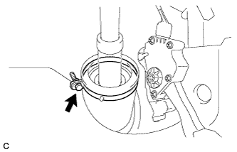
Loosen the bolt.
-
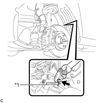
Text in Illustration *1 Matchmark Put matchmarks on the steering intermediate shaft assembly and power steering link assembly.
Note
Do not separate the steering intermediate shaft assembly from the power steering link assembly.
-
Remove the bolt.
-
Separate the steering intermediate shaft assembly from the power steering link assembly.
-
-
REMOVE STEERING POST ASSEMBLY
-
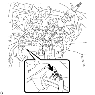
Disconnect the connector from the power steering ECU assembly.
-
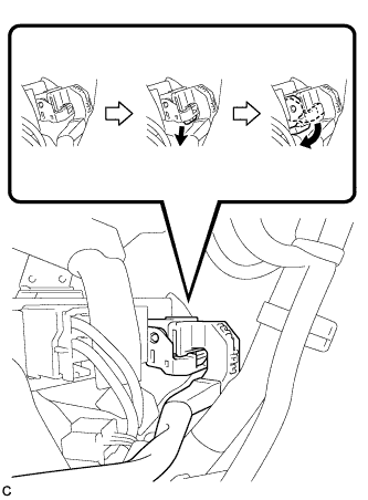
Disconnect the connector from the power steering ECU assembly.
Tech Tips
As shown in the illustration, turn the lock lever to disconnect the connector.
-
Disconnect the connectors and disengage the wire harness clamps from the steering post assembly.
-
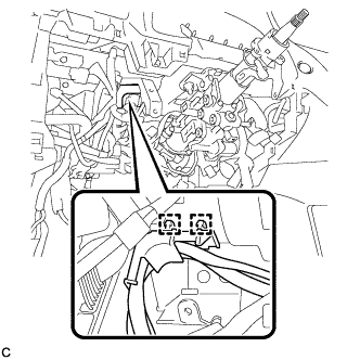
Disengage the 2 wire harness clamps.
-
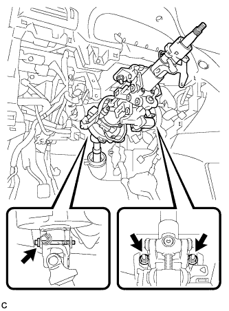
Remove the bolt, 2 nuts, and steering post assembly.
-
-
REMOVE STEERING INTERMEDIATE SHAFT ASSEMBLY
-
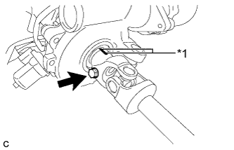
Text in Illustration *1 Matchmark Remove the bolt.
-
Put matchmarks on the steering intermediate shaft assembly and steering column assembly.
-
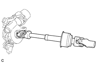
Remove the steering intermediate shaft assembly from the steering column assembly.
-