POWER STEERING SYSTEM, Diagnostic DTC:C1552

| DTC Code | DTC Name |
|---|---|
| C1552 | PIG Power Supply Voltage Malfunction |
DESCRIPTION
If a problem occurs in the power steering system, the power source relay circuit is shut off to stop the power assist.
| DTC No. | DTC Detection Condition | Trouble Area |
|---|---|---|
| C1552 | PIG power source circuit malfunction inside ECU |
|
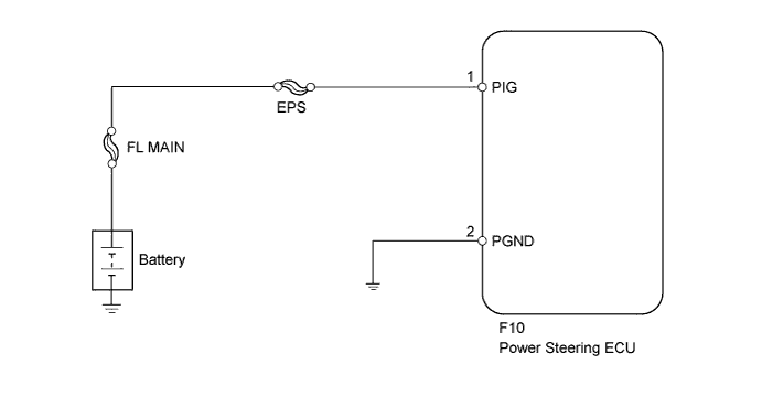
WIRING DIAGRAM
INSPECTION PROCEDURE
Note
-
If the power steering ECU has been replaced with a new one, perform the rotation angle sensor initialization and torque sensor zero point calibration Click here.
-
Inspect the fuses for circuits related to this system before performing the following inspection procedure.
PROCEDURE
-
READ VALUE USING INTELLIGENT TESTER (PIG POWER SUPPLY)
-
Turn the engine switch off.
-
Connect the intelligent tester to the DLC3.
-
Turn the engine switch on (IG).
-
Turn the intelligent tester on.
-
Enter the following menus: Chassis / EMPS / Data List.
-
Select the item "PIG Power Supply" in the Data List and read the value displayed on the intelligent tester.
EMPS Tester Display Measurement Item/Range Normal Condition Diagnostic Note PIG Power Supply Power source voltage to active motor/
Min.: 0 V
Max.: 20.1531 V
11 to 14 V The engine is running and power steering is operating. OK The normal condition value is displayed on the intelligent tester.
NG 
CHECK HARNESS AND CONNECTOR (POWER STEERING ECU - BATTERY AND BODY GROUND) Click here
OK 
REPLACE POWER STEERING ECU Click here
-
-
CHECK HARNESS AND CONNECTOR (POWER STEERING ECU - BATTERY AND BODY GROUND)
-
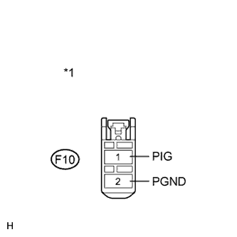
Text in Illustration *1 Front view of wire harness connector
(to Power Steering ECU)
Disconnect the connector from the power steering ECU.
-
Measure the voltage according to the value(s) in the table below.
Standard Voltage Tester Connection Condition Specified Condition F10-1 (PIG) - Body ground Always 11 to 14 V -
Measure the resistance according to the value(s) in the table below.
Standard Resistance Tester Connection Condition Specified Condition F10-2 (PGND) - Body ground Always Below 1 Ω
NG 
REPAIR OR REPLACE HARNESS OR CONNECTOR
OK
REPLACE POWER STEERING ECU Click here
-