PARKING BRAKE PEDAL (for LHD) REMOVAL

CAUTION:
Some of these service operations affect the SRS airbag system. Read the precautionary notices concerning the SRS airbag system before servicing Click here.
-
PRECAUTION (w/ Navigation System for HDD)
Note
After the engine switch is turned off, the display and navigation module display (HDD navigation system) records various types of memory and settings. As a result, after turning the engine switch off, make sure to wait for the time specified in the following table before disconnecting the cable from the negative (-) battery terminal.
Waiting Time before Disconnecting Cable from Negative (-) Battery Terminal Specification Waiting Time w/o Telematics transceiver 60 sec. w/ Telematics transceiver 120 sec. -
PRECAUTION (w/ Air Suspension)
Note
Be sure to read Precaution thoroughly before servicing Click here.
-
REMOVE FRONT SEAT ASSEMBLY LH
Tech Tips
Refer to the instructions for Removal of the front seat assembly Click here.
-
REMOVE REAR CONSOLE BOX ASSEMBLY
Tech Tips
Refer to the instructions for Removal of the rear console box assembly Click here.
-
REMOVE DRIVER SIDE KNEE AIRBAG ASSEMBLY
Tech Tips
Refer to the instructions for Removal of the driver side knee airbag assembly Click here.
-
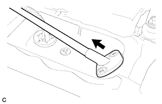
REMOVE INSTRUMENT PANEL FINISH PANEL
-
Pull the instrument panel finish panel in the direction indicated by the arrow to disengage the claw, 2 clips and 2 guides, and remove the instrument panel finish panel.
-
-
REMOVE FRONT CONSOLE BOX COVER
-
Using moulding remover A, disengage the 2 clips and 5 guides.
-
Disconnect the connector and remove the front console box cover.
-
-
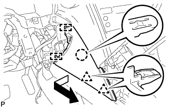
REMOVE CONSOLE BOX
-
Remove the 5 screws <D>.
-
Text in Illustration *1 Clamp *2 Guide Disengage the 2 clamps.
-
Remove the 3 clips.
-
Disengage the 3 guides and remove the console box as shown in the illustration.
-
-
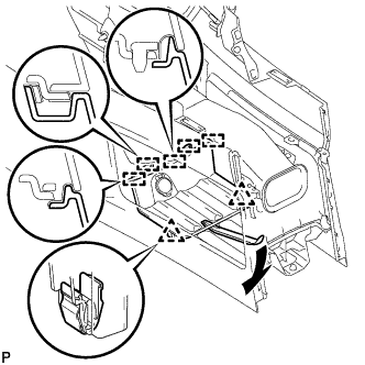
REMOVE REAR NO. 2 AIR DUCT
-
Turn back the front floor carpet.
-
Remove the clip and rear No. 2 air duct.
-
-
REMOVE REAR NO. 1 AIR DUCT
-
Disengage the wire harness clamp.
-
Remove the rear No. 1 air duct.
-
-
REMOVE FRONT FLOOR FOOTREST
-
Disengage the 2 clips to remove the front floor footrest.
-
-
LOOSEN ADJUSTING NUT
-
Text in Illustration *1 Lock Nut *2 Adjusting Nut Remove the lock nut and loosen the adjusting nut.
-
-
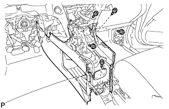
REMOVE CENTER FRONT FLOOR COVER
-
Remove the 4 bolts, 2 screws and nut.
-
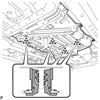
Disengage the 4 clips to remove the center front floor cover.
-
-
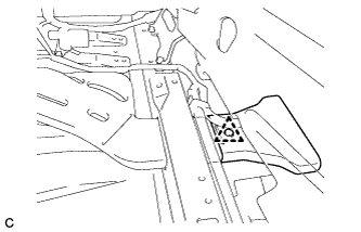
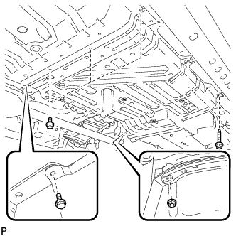
REMOVE REAR ENGINE SERVICE COVER ASSEMBLY
-
Remove the 2 bolts and rear engine service cover assembly.
-
-
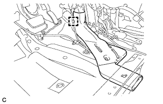
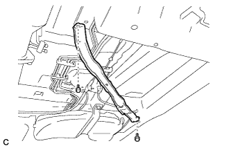
SEPARATE NO. 3 PARKING BRAKE CABLE ASSEMBLY
-
Separate the No. 3 parking brake cable assembly from the parking brake equalizer.
-
-
SEPARATE NO. 2 PARKING BRAKE CABLE ASSEMBLY
Tech Tips
Perform the same procedure as for the No. 3 parking brake cable assembly.
-
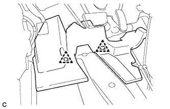
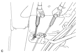
REMOVE PARKING BRAKE EQUALIZER
-
Slide the rubber boot as shown in the illustration.
-
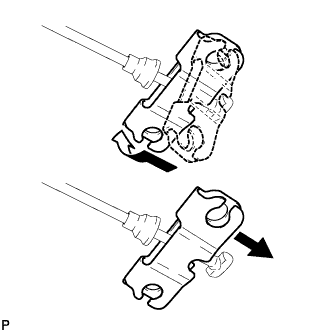
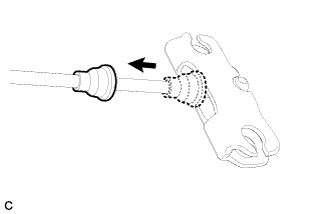
Remove the parking brake equalizer from the No. 1 parking brake cable assembly as shown in the illustration.
-
-
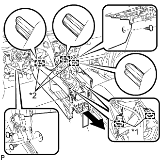
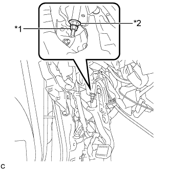
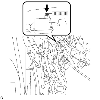
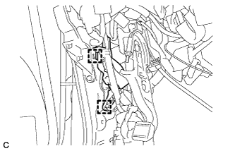
REMOVE INSTRUMENT PANEL JUNCTION BLOCK ASSEMBLY
-
Disconnect the connectors from the instrument panel junction block assembly and power management control ECU.
-
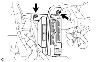
Remove the 2 nuts.
-
Disconnect the connectors from the back of the instrument panel junction block assembly.
-
-
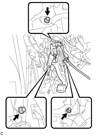
REMOVE PARKING BRAKE CONTROL PEDAL ASSEMBLY
-
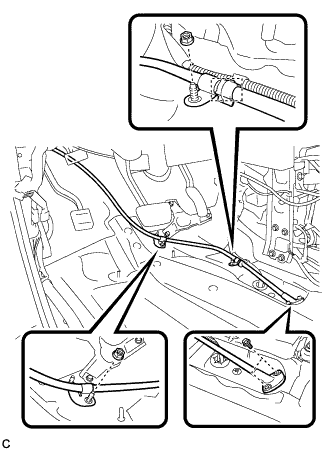
Remove the 2 bolts and 2 nuts, and separate the No. 1 parking brake cable assembly.
-
Remove the clamp.
-
Pull out the No. 1 parking brake cable assembly toward the cabin.
-
Disconnect the parking brake switch connector.
-
Disengage the 2 clamps to separate the wire harness clamp.
-
Remove the 3 nuts and parking brake control pedal assembly.
-