POWER STEERING ECU INSTALLATION

-
INSTALL POWER STEERING ECU ASSEMBLY (for LHD)
-
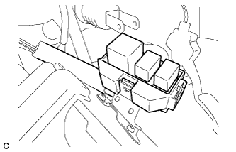
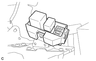
Install the relay block sub-assembly.
-
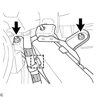
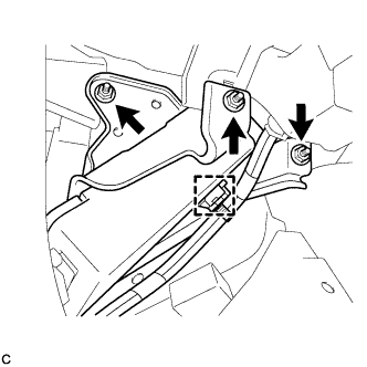
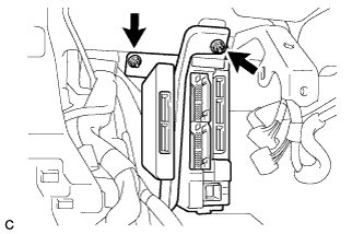
Install the power steering ECU assembly with the 2 nuts and clamp.
- Torque:
- 8.5 N*m { 87 kgf*cm, 75 in.*lbf }
-
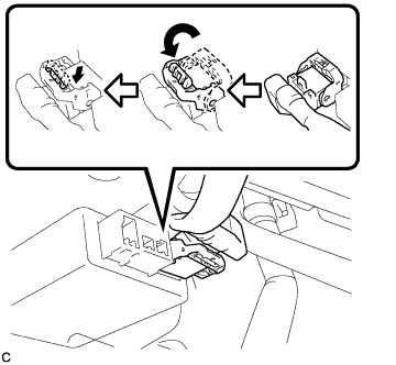
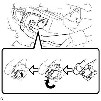
Securely connect the connector to the power steering ECU assembly.
Tech Tips
Return the lock lever to its original position to connect the connector, and then securely push in the lock of the lock lever as shown in the illustration.
-
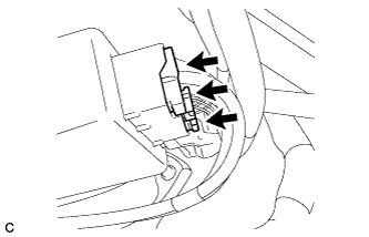
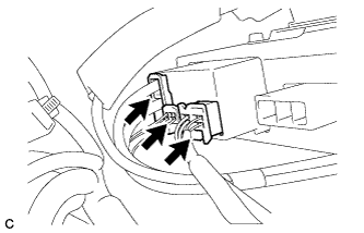
Connect the 3 connectors to the power steering ECU assembly.
-
-
INSTALL POWER STEERING ECU ASSEMBLY (for RHD)
-
Install the relay block sub-assembly.
-
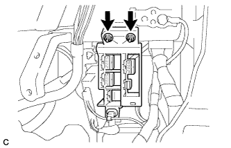
Install the power steering ECU assembly with the 3 nuts and clamp.
- Torque:
- 8.5 N*m { 87 kgf*cm, 75 in.*lbf }
-
Connect the 3 connectors to the power steering ECU assembly.
-
Securely connect the connector to the power steering ECU assembly.
Tech Tips
Return the lock lever to its original position to connect the connector, and then securely push in the lock of the lock lever as shown in the illustration.
-
-
INSTALL AFS ECU (for LHD)
Tech Tips
Refer to the instructions for Installation of the AFS ECU Click here.
-
INSTALL CONNECTOR HOLDER (for RHD)
-
Install the connector holder with the 2 nuts.
- Torque:
- 5.5 N*m { 56 kgf*cm, 49 in.*lbf }
-
-
INSTALL INSTRUMENT PANEL JUNCTION BLOCK ASSEMBLY (for LHD)
-
Connect the connectors to the back of the instrument panel junction block assembly.
-
Install the instrument panel junction block assembly with the 2 nuts.
- Torque:
- 8.0 N*m { 82 kgf*cm, 71 in.*lbf }
-
Connect the connectors to the instrument panel junction block assembly.
-
-
INSTALL BRAKE PEDAL SUPPORT SUB-ASSEMBLY (for LHD)
Tech Tips
Refer to the instructions for Installation of the brake pedal support sub-assembly Click here.
-
INSTALL BRAKE PEDAL SUPPORT SUB-ASSEMBLY (for RHD)
Tech Tips
Refer to the instructions for Installation of the brake pedal support sub-assembly Click here.
-
CONNECT CABLE TO NEGATIVE BATTERY TERMINAL
Note
When disconnecting the cable, some systems need to be initialized after the cable is reconnected Click here.
-
INITIALIZE ROTATION ANGLE SENSOR AND CALIBRATE TORQUE SENSOR ZERO POINT
Tech Tips
-
INSPECT FOR SRS WARNING LIGHT
Tech Tips