- Click here
INSTALL POWER STEERING ECU ASSEMBLY (for LHD)
-
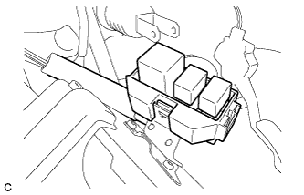
Install the relay block sub-assembly.
-
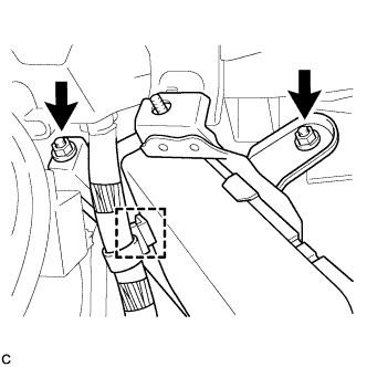
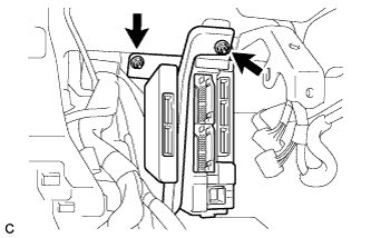
Install the power steering ECU assembly with the 2 nuts and clamp.
8.5 N*m 87 kgf*cm 75 in.*lbf -
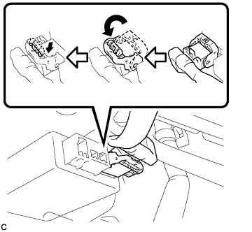
Securely connect the connector to the power steering ECU assembly.
Tip:Return the lock lever to its original position to connect the connector, and then securely push in the lock of the lock lever as shown in the illustration.
-
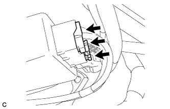
Connect the 3 connectors to the power steering ECU assembly.
-
- Click here
INSTALL POWER STEERING ECU ASSEMBLY (for RHD)
-
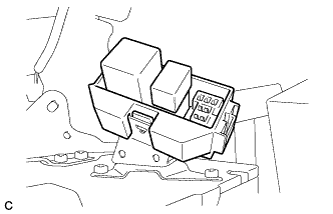
Install the relay block sub-assembly.
-
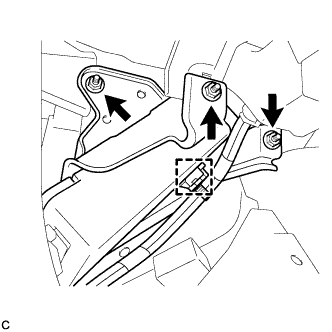
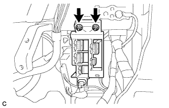
Install the power steering ECU assembly with the 3 nuts and clamp.
8.5 N*m 87 kgf*cm 75 in.*lbf -
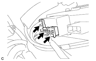
Connect the 3 connectors to the power steering ECU assembly.
-
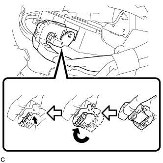
Securely connect the connector to the power steering ECU assembly.
Tip:Return the lock lever to its original position to connect the connector, and then securely push in the lock of the lock lever as shown in the illustration.
-
- Click here
INSTALL AFS ECU (for LHD)
Tip:Refer to the instructions for Installation of the AFS ECU (Click here).
- Click here
INSTALL CONNECTOR HOLDER (for RHD)
-
Install the connector holder with the 2 nuts.
5.5 N*m 56 kgf*cm 49 in.*lbf
-
- Click here
INSTALL INSTRUMENT PANEL JUNCTION BLOCK ASSEMBLY (for LHD)
-
Connect the connectors to the back of the instrument panel junction block assembly.
-
Install the instrument panel junction block assembly with the 2 nuts.
8.0 N*m 82 kgf*cm 71 in.*lbf -
Connect the connectors to the instrument panel junction block assembly.
-
- Click here
INSTALL BRAKE PEDAL SUPPORT SUB-ASSEMBLY (for LHD)
Tip:Refer to the instructions for Installation of the brake pedal support sub-assembly (Click here).
- Click here
INSTALL BRAKE PEDAL SUPPORT SUB-ASSEMBLY (for RHD)
Tip:Refer to the instructions for Installation of the brake pedal support sub-assembly (Click here).
- Click here
CONNECT CABLE TO NEGATIVE BATTERY TERMINAL
Note:When disconnecting the cable, some systems need to be initialized after the cable is reconnected (Click here).
- Click here
INITIALIZE ROTATION ANGLE SENSOR AND CALIBRATE TORQUE SENSOR ZERO POINT
Tip: - Click here
INSPECT FOR SRS WARNING LIGHT
Tip: