POWER STEERING ECU REMOVAL

CAUTION:
Be sure to read Precaution thoroughly before servicing Click here.
-
FRONT WHEELS FACING STRAIGHT AHEAD
-
PRECAUTION (w/ Navigation System for HDD)
Note
After the engine switch is turned off, the display and navigation module display (HDD navigation system) records various types of memory and settings. As a result, after turning the engine switch off, make sure to wait for the time specified in the following table before disconnecting the cable from the negative (-) battery terminal.
Waiting Time before Disconnecting Cable from Negative (-) Battery Terminal Specification Waiting Time w/o Telematics transceiver 60 sec. w/ Telematics transceiver 120 sec. -
DISCONNECT CABLE FROM NEGATIVE BATTERY TERMINAL
CAUTION:
Wait at least 90 seconds after disconnecting the cable from the negative (-) battery terminal to disable the SRS system.
Note
When disconnecting the cable, some systems need to be initialized after the cable is reconnected Click here.
-
REMOVE BRAKE PEDAL SUPPORT SUB-ASSEMBLY (for LHD)
Tech Tips
Refer to the instructions for Removal of the brake pedal support sub-assembly Click here.
-
REMOVE BRAKE PEDAL SUPPORT SUB-ASSEMBLY (for RHD)
Tech Tips
Refer to the instructions for Removal of the brake pedal support sub-assembly Click here.
-
REMOVE INSTRUMENT PANEL JUNCTION BLOCK ASSEMBLY (for LHD)
-
Disconnect the connectors from the instrument panel junction block assembly and power management control ECU.
-
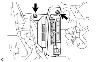
Remove the 2 nuts.
-
Disconnect the connectors from the back of the instrument panel junction block assembly.
-
-
REMOVE CONNECTOR HOLDER (for RHD)
-
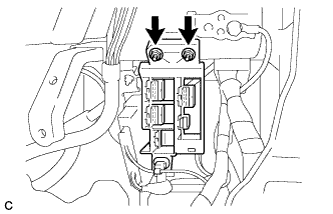
Remove the 2 nuts and connector holder.
-
-
REMOVE AFS ECU (for LHD)
Tech Tips
Refer to the instructions for Removal of the AFS ECU Click here.
-
REMOVE POWER STEERING ECU ASSEMBLY (for LHD)
-
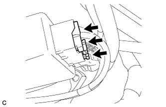
Disconnect the 3 connectors from the power steering ECU assembly.
-
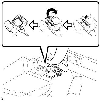
Disconnect the connector from the power steering ECU assembly.
Tech Tips
Pull out the lock of the lock lever, disengage the claw, and raise the lock lever to disconnect the connector as shown in the illustration.
-
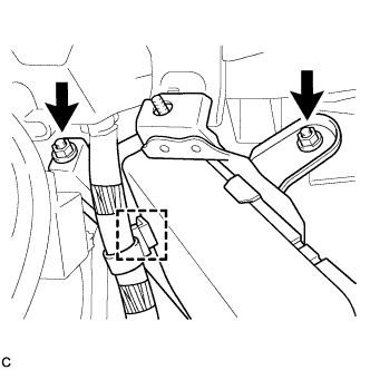
Remove the 2 nuts, clamp and power steering ECU assembly.
-
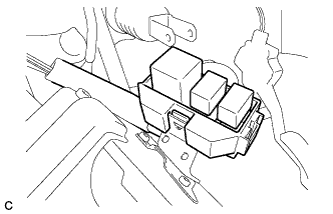
Remove the relay block sub-assembly.
-
-
REMOVE POWER STEERING ECU ASSEMBLY (for RHD)
-
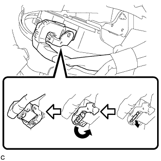
Disconnect the connector from the power steering ECU assembly.
Tech Tips
Pull out the lock of the lock lever, disengage the claw, and raise the lock lever to disconnect the connector as shown in the illustration.
-
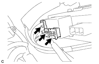
Disconnect the 3 connectors from the power steering ECU assembly.
-
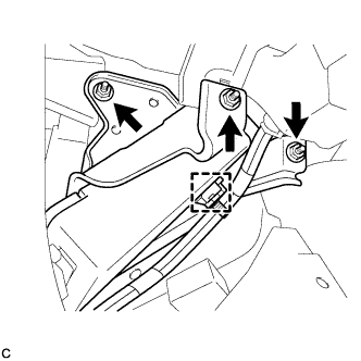
Remove the 3 nuts, clamp and power steering ECU assembly.
-
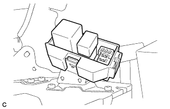
Remove the relay block sub-assembly.
-