- Click here
INSTALL BRAKE BOOSTER GASKET
-
Install a new brake booster gasket to the brake booster assembly.
-
- Click here
TEMPORARILY TIGHTEN BRAKE BOOSTER ASSEMBLY
-
Temporarily install the brake booster assembly to the body.
Note:Do not kink or damage the brake lines.
-
- Click here
TEMPORARILY TIGHTEN BRAKE MASTER CYLINDER PUSH ROD CLEVIS
-
Temporarily install the lock nut and brake master cylinder push rod clevis to the brake booster assembly.
-
- Click here
INSTALL BRAKE BOOSTER ASSEMBLY
-

Install the brake booster assembly with the 4 nuts.
13 N*m 130 kgf*cm 9 ft.*lbf Note:Do not kink or damage the brake lines.
-
- Click here
CONNECT BRAKE MASTER CYLINDER PUSH ROD CLEVIS
-
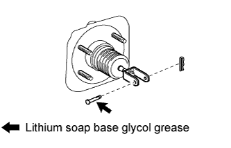
Apply lithium soap base glycol grease to the push rod pin.
-
Connect the brake master cylinder push rod clevis to the brake pedal with the push rod pin, and install a new clip as shown in the illustration.
-
- Click here
INSTALL BRAKE PEDAL RETURN SPRING
-
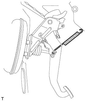
Install the brake pedal return spring between the instrument panel reinforcement and push rod pin.
-
- Click here
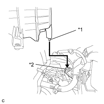
INSTALL NO. 1 INSTRUMENT PANEL UNDER COVER SUB-ASSEMBLY
-
Engage each clamp.
-
Connect each connector.
-
Engage the claw and 2 guides.
-
Install the No. 1 instrument panel under cover sub- assembly with the 2 screws <D>.
-
- Click here
CONNECT BRAKE LINE
-
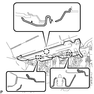
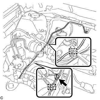
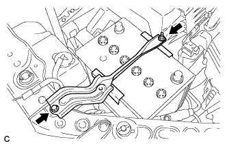
Engage the 5 clamps and install the brake lines.
-
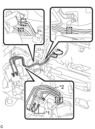
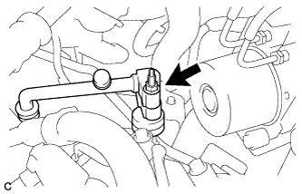
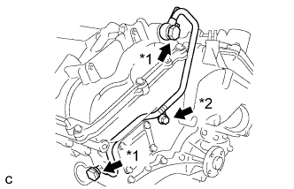
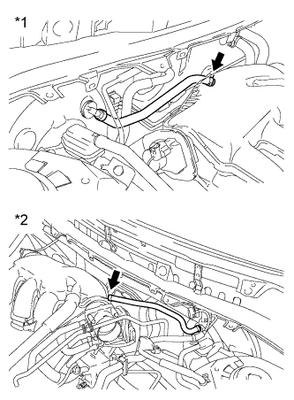
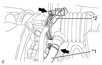
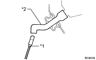
Using a union nut wrench, connect the front brake tube*1 and No. 8 front brake tube*2 to the brake actuator assembly.
Table 1. Text in Illustration *1 Front Brake Tube *2 No. 8 Front Brake Tube *1 20 N*m 199 kgf*cm 14 ft.*lbf *2 15 N*m 155 kgf*cm 11 ft.*lbf Note:
-
Do not kink or damage the brake lines.
-
Do not allow any foreign matter such as dirt and dust to enter the brake lines.
-
Use the formula to calculate special torque values for situations where the union nut wrench is combined with a torque wrench (Click here).
-
-
Using a union nut wrench, connect the No. 8 front brake tube to the front brake flexible hose RH.
15 N*m 155 kgf*cm 11 ft.*lbf Note:
-
Do not kink or damage the brake line.
-
Do not allow any foreign matter such as dirt and dust to enter the brake line.
-
Use the formula to calculate special torque values for situations where the union nut wrench is combined with a torque wrench (Click here).
-
-
- Click here
INSTALL AIR CONDITIONING TUBE AND ACCESSORY ASSEMBLY
-
Install the tube clamp to the body.
Note:Do not damage the clamp.
-
Remove the attached vinyl tape from the pipe.
-
Sufficiently apply compressor oil to 2 new O-rings and the fitting surface of the air conditioning tube and accessory assembly and cooler condenser assembly.
Compressor oil ND-OIL 8 or equivalent -
Install the 2 O-rings on the air conditioning tube and accessory assembly.
Note:Keep the O-ring and O-ring fitting surfaces free from dirt or any foreign objects.
-
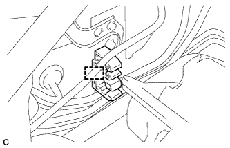
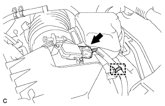
Engage the 2 clamps and connect the connector.
Note:
-
Do not deform the piping.
-
Do not damage the plastic clamp.
-
-
Connect the air conditioning tube and accessory assembly to the cooler condenser assembly with the bolt.
5.4 N*m 55 kgf*cm 48 in.*lbf -
Install the air conditioning tube and accessory assembly to the air conditioning unit.
Note:Insert the pipe joint into the fitting hole securely.
-
- Click here
INSTALL SUCTION PIPE SUB-ASSEMBLY
-
Remove the attached vinyl tape from the pipe.
-
Sufficiently apply compressor oil to a new O-ring and the fitting surface of the suction hose sub-assembly.
Compressor oil ND-OIL 8 or equivalent -
Install the O-ring on the suction hose sub-assembly.
Note:Keep the O-ring and O-ring fitting surfaces free from dirt or any foreign objects.
-
Connect the suction pipe sub-assembly to the air conditioning unit.
Note:
-
Insert the pipe joint into the fitting hole securely.
-
Do not deform the piping.
-
Do not damage the plastic clamp.
-
-
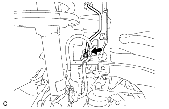
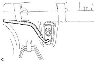
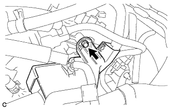
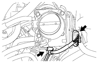
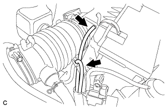
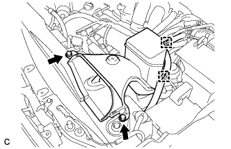
Engage the clamp.
-
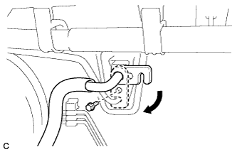
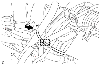
Move the hook connector in the direction indicated by the arrow in the illustration, and install the bolt.
9.8 N*m 100 kgf*cm 87 in.*lbf -
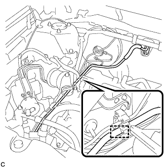
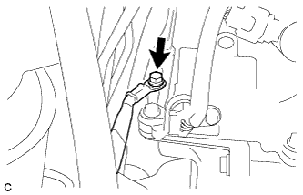
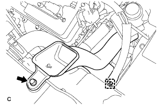
Install the suction pipe bracket to the brake actuator bracket with the bolt.
9.8 N*m 100 kgf*cm 87 in.*lbf
-
- Click here
INSTALL SUCTION HOSE SUB-ASSEMBLY
-
Remove the attached vinyl tape from the hose.
-
Sufficiently apply compressor oil to a new O-ring and the fitting surface of the suction hose sub-assembly.
Compressor oil ND-OIL 8 or equivalent -
Install the O-ring on the suction hose sub-assembly.
Note:Keep the O-ring and O-ring fitting surfaces free from dirt or any foreign objects.
-
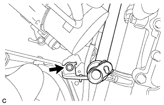
Connect the suction hose sub-assembly to the suction pipe sub-assembly with the nut.
9.8 N*m 100 kgf*cm 87 in.*lbf Note:Do not deform the piping.
-
- Click here
INSTALL WIRE HARNESS (for 1AR-FE)
-
Engage the 4 clamps to install the wire harness.
-
- Click here
INSTALL CYLINDER HEAD COVER SUB-ASSEMBLY (for 2GR-FE)
-
Apply seal packing as shown in the illustration.
Table 2. Text in Illustration 
Seal Packing Seal Packing Toyota Genuine Seal Packing Black, Three Bond 1207B or equivalent Note:
-
Remove any oil from the contact surface.
-
Install the cylinder head cover sub-assembly within 3 minutes of applying seal packing.
-
Do not start the engine for at least 2 hours after installation.
-
-
Install 3 new gaskets shown in the illustration.
-
Install a new cylinder head cover gasket to the cylinder head cover sub-assembly.
-
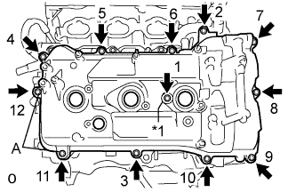
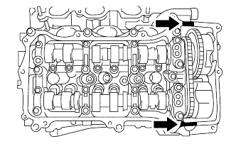
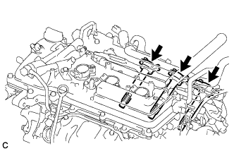
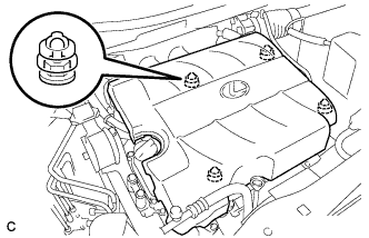
Install the cylinder head cover sub-assembly with the 12 bolts and a new seal washer.
Table 3. Text in Illustration *1 Seal Washer Bolt A 21 N*m 214 kgf*cm 15 ft.*lbf Except bolt A 10 N*m 102 kgf*cm 7 ft.*lbf Tip:After tightening all bolts, check the tightening torque of 1 and 11. Retighten the bolt if necessary.
-
- Click here
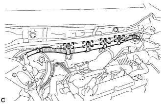
INSTALL ENGINE WIRE (for 2GR-FE)
-
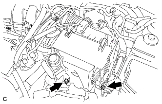
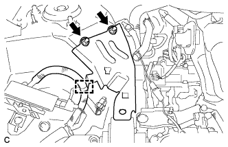
Install the wire harness protector with the bolt.
8.4 N*m 86 kgf*cm 74 in.*lbf -
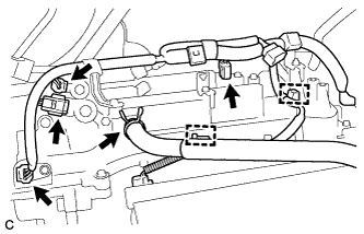
Connect the 4 connectors and ventilation hose, and engage the 2 clamps.
-
Install the ground cable with the bolt.
8.4 N*m 86 kgf*cm 74 in.*lbf
-
- Click here
INSTALL OIL PIPE (for 2GR-FE)
-
Make sure that there is no foreign matter on the mesh of the oil control valve filter RH.
Note:Do not touch the mesh when installing the oil control valve filter RH.
-
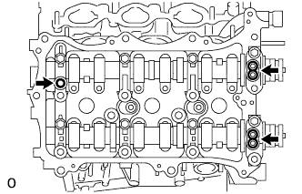
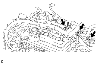
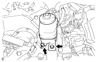
Install the oil control valve filter RH to the oil pipe union. Install 2 new gaskets and temporarily install the oil pipe (on the cylinder head cover sub-assembly side) with the oil pipe union.
Table 4. Text in Illustration *1 Oil Pipe Union *2 Bolt -
Install a new gasket and temporarily install the oil pipe (on the cylinder head sub-assembly side) with the oil pipe union.
-
Install the bolt to the cylinder head sub-assembly.
10 N*m 102 kgf*cm 7 ft.*lbf -
Tighten the oil pipe union (on the cylinder head cover sub-assembly side).
65 N*m 663 kgf*cm 48 ft.*lbf -
Tighten the oil pipe union (on the cylinder head sub-assembly side).
65 N*m 663 kgf*cm 48 ft.*lbf Note:If the link that connects the gaskets is broken, remove the connecting link by using side cutters or a similar tool.
-
- Click here
INSTALL NO. 2 TIMING GEAR COVER (for 2GR-FE)
-
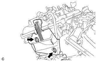
Install the No. 2 timing gear cover with the 2 bolts.
6.0 N*m 61 kgf*cm 53 in.*lbf
-
- Click here
INSTALL IGNITION COIL ASSEMBLY (for 2GR-FE)
-
Install the 3 ignition coil assemblies with the 3 bolts.
10 N*m 102 kgf*cm 7 ft.*lbf -
Connect the 3 connectors.
-
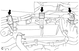
Engage the 3 clamps.
-
- Click here
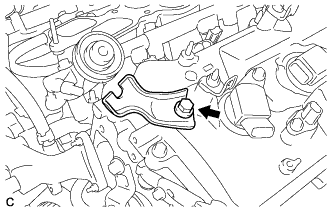
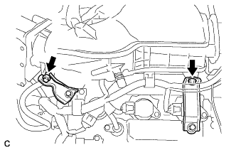
INSTALL NO. 1 SURGE TANK STAY (for 2GR-FE)
-
Install the No. 1 surge tank stay with the bolt.
21 N*m 214 kgf*cm 15 ft.*lbf
-
- Click here
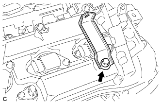
INSTALL THROTTLE BODY BRACKET (for 2GR-FE)
-
Install the throttle body bracket with the bolt.
21 N*m 214 kgf*cm 15 ft.*lbf
-
- Click here
INSTALL INTAKE AIR SURGE TANK ASSEMBLY (for 2GR-FE)
NOTICE DO NOT apply oil to the bolts listed below: Tightening Part Surge Tank and Intake Manifold No. 1 Surge Tank Stay and Surge Tank Throttle Body Bracket and Surge Tank
-
Install 3 new air surge tank to intake manifold gaskets to the intake air surge tank.
-
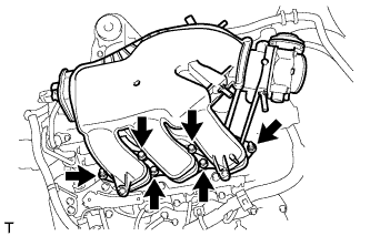
Using a 5 mm hexagon socket wrench, install the intake air surge tank assembly with the 4 bolts and 2 nuts.
Bolt 18 N*m 184 kgf*cm 13 ft.*lbf Nut 16 N*m 163 kgf*cm 12 ft.*lbf -
Install the throttle body bracket and No. 1 surge tank stay with the 2 bolts.
21 N*m 214 kgf*cm 15 ft.*lbf -
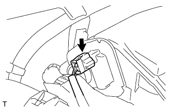
Connect the connector to the intake air control valve assembly.
-
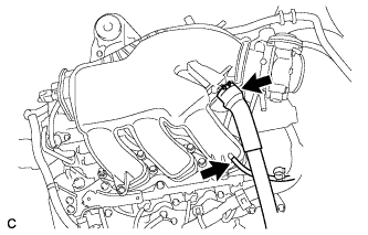
Connect the ventilation hose and vacuum hose.
-
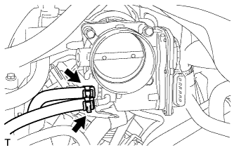
Connect the 2 water by-pass hoses to the throttle body assembly.
-
Connect the vacuum hose clamp and fuel vapor feed hose.
-
Connect the throttle body assembly connector and wire harness clamp to the throttle body assembly.
-
Connect the union to check valve hose.
Table 5. Text in Illustration *1 for RHD: *2 for LHD:
-
- Click here
INSTALL AIR CLEANER ASSEMBLY (for 2GR-FE)
-
Insert the tab of the air cleaner assembly to the hole of the vehicle body as shown in the illustration.
Table 6. Text in Illustration *1 Tab *2 Hole -
Install the air cleaner assembly with the 2 bolts.
5.5 N*m 56 kgf*cm 49 in.*lbf -
Connect the air cleaner hose to the throttle body with the hose clamp.
Table 7. Text in Illustration *1 Ventilation Hose *2 Fuel Vapor Feed Hose -
Connect the ventilation hose and the fuel vapor feed hose.
-
Connect the 2 vacuum hoses.
-
Connect the 2 wire harness clamps and vacuum switching valve connector.
-
Connect the vacuum hose to the intake air surge tank assembly.
-
Install the hose to the hose clamp.
-
Connect the mass air flow meter connector and wire harness clamp.
-
- Click here
INSTALL BATTERY (for 2GR-FE)
-
Install the battery and battery tray.
-
Install the battery clamp with the bolt and nut.
5.4 N*m 55 kgf*cm 48 in.*lbf -
Connect the positive (+) cable to the positive (+) battery terminal.
6.4 N*m 65 kgf*cm 57 in.*lbf
-
- Click here
INSTALL NO. 1 AIR CLEANER INLET (for 2GR-FE)
-
Install the No. 1 air cleaner inlet with the bolt.
8.0 N*m 82 kgf*cm 71 in.*lbf -
Connect the vacuum hose clamp to the No. 1 air cleaner inlet.
-
- Click here
INSTALL NO. 2 AIR CLEANER INLET (for 2GR-FE)
-
Install the No. 2 air cleaner inlet with the 2 bolts.
8.0 N*m 82 kgf*cm 71 in.*lbf -
Connect the 2 vacuum hose clamps to the No. 2 air cleaner inlet.
-
- Click here
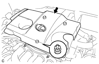
INSTALL V-BANK COVER SUB-ASSEMBLY (for 2GR-FE)
-
Fit the 4 retainers and install the V-bank cover sub-assembly.
-
- Click here
INSTALL RESERVOIR BRACKET
-
Install the reservoir bracket with the 2 nuts.
19 N*m 194 kgf*cm 14 ft.*lbf -
Engage the clamp.
-
- Click here
INSTALL BRAKE MASTER CYLINDER RESERVOIR ASSEMBLY
-
Install the brake master cylinder reservoir assembly with the bolt.
9.0 N*m 92 kgf*cm 80 in.*lbf -
Connect the connector.
-
- Click here
INSTALL CHECK VALVE GROMMET
-
Install a new check valve grommet to the brake booster assembly.
-
- Click here
INSTALL BRAKE VACUUM CHECK VALVE ASSEMBLY
-
Install the vacuum check valve assembly to the brake booster assembly.
-
- Click here
INSTALL VACUUM SWITCHING VALVE ASSEMBLY (for 1AR-FE)
-
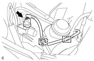
Install the vacuum switching valve assembly with the bolt.
9.0 N*m 92 kgf*cm 80 in.*lbf -
Connect the 2 vacuum hoses and connector.
-
Connect the union to connector tube hose and wire harness clamp.
-
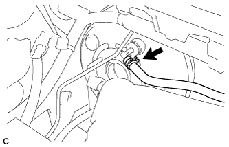
- Click here
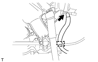
CONNECT VACUUM HOSE (for 1AR-FE)
-
Connect the vacuum hose to the vacuum check valve assembly and slide the clip.
-
- Click here
INSTALL NO. 1 ENGINE COVER SUB-ASSEMBLY (for 1AR-FE)
-
Fit the 3 retainers and install the No. 1 engine cover sub-assembly.
-
- Click here
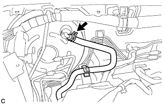
CONNECT VACUUM HOSE (for 2GR-FE)
-
Connect the vacuum hose to the vacuum check valve assembly and slide the clip.
-
- Click here
CONNECT CABLE TO NEGATIVE BATTERY TERMINAL
Note:When disconnecting the cable, some systems need to be initialized after the cable is reconnected (Click here).
- Click here
INSTALL BRAKE MASTER CYLINDER SUB-ASSEMBLY
- Click here
ADD ENGINE COOLANT (for 2GR-FE)
-
Tighten the radiator drain cock plug by hand.
-
Tighten the cylinder block drain cock plug. (for Bank 1)
13 N*m 130 kgf*cm 9 ft.*lbf -
Tighten the cylinder block drain cock plug. (for Bank 2, w/ Cylinder Block Drain Cock Plug)
13 N*m 130 kgf*cm 9 ft.*lbf -
Loosen the air drain cock plug on the water inlet housing.
-
Add engine coolant to the radiator inlet opening until engine coolant overflows from the air drain cock hole. Then tighten the air drain cock plug to the water inlet housing.
13 N*m 130 kgf*cm 9 ft.*lbf -
Slowly fill the radiator assembly with engine coolant.
Standard capacity 9.5 liters (10.0 US qts, 8.3 Imp. qts) Note:Do not substitute plain water for engine coolant.
Tip:TOYOTA vehicles are filled with TOYOTA SLLC at the factory. In order to avoid damage to the engine cooling system and other technical problems, only use TOYOTA SLLC or similar high quality ethylene glycol based non-silicate, non-amine, non-nitrite, non-borate coolant with long-life hybrid organic acid technology (coolant with long-life hybrid organic acid technology is a combination of low phosphates and organic acids).
-
Remove the reserve tank cap.
-
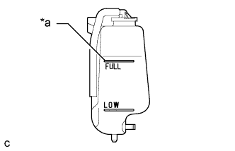
Slowly pour engine coolant into the radiator reserve tank assembly until it reaches the full line.
Table 8. Text in Illustration *a Full Line -
Squeeze the No. 1 radiator hose and No. 2 radiator hose several times by hand, and then check the level of the engine coolant.
If the engine coolant level is low, add engine coolant.
-
Install the radiator cap sub-assembly and reserve tank cap.
-
Bleed air from the cooling system.
Note:
-
Before starting the engine, turn the A/C switch off.
-
Adjust the heater control to the maximum hot setting.
-
Adjust the blower speed to the low setting.
-
Warm up the engine until the thermostat opens. While the thermostat is open, circulate the engine coolant for several minutes.
Tip:The thermostat open timing can be confirmed by squeezing the No. 2 radiator hose by hand, and sensing vibrations when the engine coolant starts to flow inside the No. 2 radiator hose.
-
Maintain the engine speed at 2500 to 3000 rpm.
-
Squeeze the No. 1 radiator hose and No. 2 radiator hose several times by hand to bleed air.
CAUTION:When squeezing the No. 1 radiator hose and No. 2 radiator hose:
-
Wear protective gloves.
-
Be careful as the No. 1 radiator hose and No. 2 radiator hose are hot.
-
Keep your hands away from the fan and No. 2 fan.
Note:
-
If the coolant temperature gauge indicates an excessive temperature, turn off the engine and let it cool.
-
Make sure that the radiator reserve tank assembly still has some engine coolant in it.
-
If the radiator reserve tank assembly does not have enough engine coolant, the engine may overheat or be seriously damaged.
-
If the radiator reserve tank assembly does not have enough engine coolant, perform the following: 1) stop the engine, 2) wait until the engine coolant has cooled down, and 3) add engine coolant until the radiator reserve tank assembly is filled to the full line.
-
-
-
Stop the engine, and wait until the engine coolant cools down.
-
Add engine coolant to the full line on the radiator reserve tank assembly.
-
- Click here
CHARGE WITH REFRIGERANT
-
Perform vacuum purging using a vacuum pump.
-
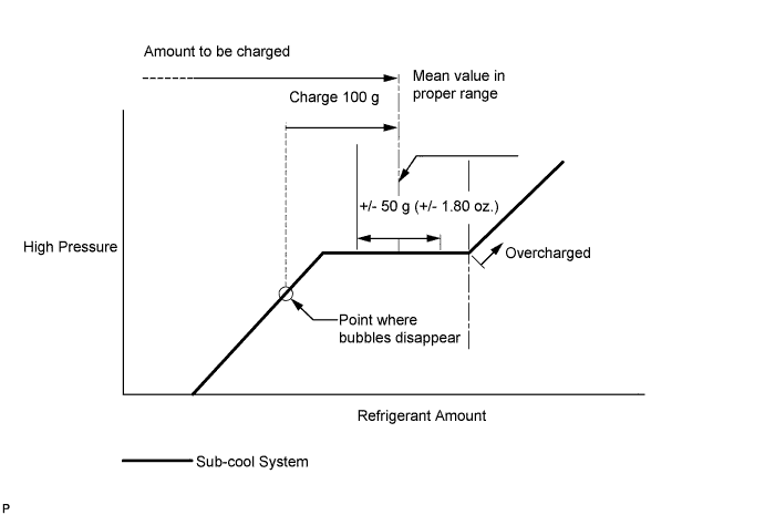
Charge with refrigerant HFC-134a (R134a).
Standard (for Suction Pipe Separate Type) 450 to 550 g (15.9 to 19.4 oz.) Standard (except Suction Pipe Separate Type) 500 to 600 g (17.6 to 21.2 oz.) 09985-20010 09985-02010 09985-02050 09985-02060 09985-02070 09985-02080 09985-02090 09985-02110 09985-02130 09985-02140 09985-02150 Note:
-
Do not turn the A/C switch on before charging with refrigerant. Doing so will cause the compressor to work without refrigerant, resulting in overheating of the compressor.
-
Approximately 100 g (3.5 oz.) of refrigerant may need to be charged after bubbles disappear. The refrigerant amount should be checked by quantity, not with the sight glass.
Tip:Ensure that sufficient refrigerant is available to recharge the system when using a refrigerant recovery unit. Refrigerant recovery units are not always able to recover 100% of the refrigerant from an A/C system.
-
-
- Click here
WARM UP ENGINE
-
Keep the A/C switch on for at least 2 minutes to warm up the compressor.
Note:Be sure to warm up the compressor when turning the A/C switch on after removing and installing the cooler refrigerant lines (including the compressor), to prevent damage to the compressor.
-
- Click here
INSPECT ENGINE OIL LEVEL (for 2GR-FE)
-
Warm up and stop the engine, then wait for 5 minutes. The oil level should be between the low level and full level marks on the engine oil level dipstick.
If the engine oil level is low, check for leakage and add oil up to the full level mark.
Note:Do not add engine oil to above the full level mark.
-
- Click here
INSPECT FOR OIL LEAK (for 2GR-FE)
- Click here
INSPECT FOR COOLANT LEAK (for 2GR-FE)
CAUTION:Do not remove the radiator cap while the engine and radiator are still hot. Pressurized, hot engine coolant and steam may be released and cause serious burns.
Note:Before performing each inspection, turn the A/C switch off.
-
Remove the radiator cap.
-
Fill the radiator with coolant and attach a radiator cap tester.
-
Warm up the engine.
-
Using the radiator cap tester, increase the pressure inside the radiator to 118 kPa (1.2 kgf/cm2, 17 psi), and check that the pressure does not drop.
If the pressure drops, check the hoses, radiator and water pump for leaks. If no external leaks are found, check the heater core, cylinder block and cylinder head.
-
Remove the radiator cap tester.
-
Install the radiator cap.
-
- Click here
INSPECT FOR REFRIGERANT LEAK
-
After recharging with refrigerant, inspect for refrigerant leaks using a halogen leak detector.
-
Carry out the test under the following conditions:
-
Turn the engine switch off.
-
Secure good ventilation (the halogen leak detector may react to volatile gases which are not refrigerant, such as evaporated gasoline and exhaust gas).
-
Repeat the test 2 or 3 times.
-
Make sure that there is some refrigerant remaining in the refrigeration system.
When the compressor is off: approx. 392 to 588 kPa (4 to 6 kgf/cm2, 57 to 85 psi)
-
-
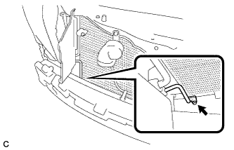
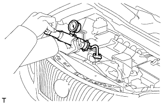
Using a halogen leak detector, inspect for refrigerant leaks from the refrigerant lines.
Table 9. Text in Illustration *1 Inspect for Leak *2 Halogen Leak Detector -
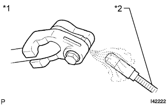
Bring the halogen leak detector close to the drain hose with the detector's power off, and then turn the detector on.
Table 10. Text in Illustration *1 Halogen Leak Detector *2 Drain Hose Tip:
-
After the blower motor has stopped, let the cooling unit stand for more than 15 minutes.
-
Bring the halogen leak detector sensor under the drain hose.
-
When bringing the halogen leak detector close to the drain hose, make sure that the halogen leak detector does not react to volatile gases. If it is not possible to avoid interference from volatile gases, the vehicle should be lifted up to allow testing.
-
-
If a refrigerant leak is not detected from the drain hose, remove the blower motor control from the cooling unit. Insert the halogen leak detector sensor into the unit and perform the test.
-
Disconnect the pressure switch connector and leave it for approximately 20 minutes. Bring the halogen leak detector close to the pressure switch and perform the test.
-
- Click here
INSTALL FRONT BUMPER COVER
for Standard: (Click here)
for Sport Package: (Click here)
- Click here
INSPECT AND ADJUST BRAKE PEDAL
- Click here
INSTALL FRONT WHEEL RH