BRAKE BOOSTER (for RHD) REMOVAL

-
PRECAUTION
Note
After the engine switch is turned off, the display and navigation module display (HDD navigation system) records various types of memory and settings. As a result, after turning the engine switch off, make sure to wait for the time specified in the following table before disconnecting the cable from the negative (-) battery terminal.
Waiting Time before Disconnecting Cable from Negative (-) Battery Terminal Specification Waiting Time w/o Telematics transceiver 60 sec. w/ Telematics transceiver 120 sec. -
RECOVER REFRIGERANT FROM REFRIGERATION SYSTEM
-
Start up the engine.
-
Turn the A/C switch on.
-
Operate the cooler compressor at an engine speed of approximately 1000 rpm for 5 to 6 minutes to circulate the refrigerant. This causes most of the compressor oil from the various components of the A/C system to collect in the A/C compressor.
-
Stop the engine.
-
Recover the refrigerant from the A/C system using a refrigerant recovery unit.
-
-
DISCONNECT CABLE FROM NEGATIVE BATTERY TERMINAL
Note
When disconnecting the cable, some systems need to be initialized after the cable is reconnected Click here.
-
REMOVE BRAKE MASTER CYLINDER SUB-ASSEMBLY
-
REMOVE FRONT BUMPER COVER
for Standard: Click here
for Sport Package: Click here
-
REMOVE FRONT WHEEL RH
-
REMOVE NO. 1 ENGINE COVER SUB-ASSEMBLY (for 1AR-FE)
-
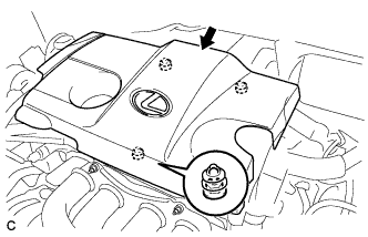
Lift the rear of the No. 1 engine cover sub-assembly to detach the cover from the 2 pins, and then lift the front of the No. 1 engine cover sub-assembly to detach the cover from the pin and remove the No. 1 engine cover sub-assembly.
Note
Attempting to disengage both front and rear clips at the same time may cause the No. 1 engine cover sub-assembly to break.
-
-
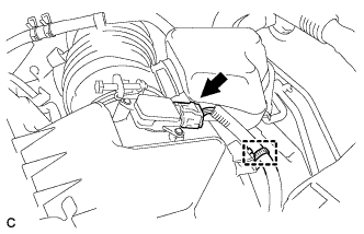
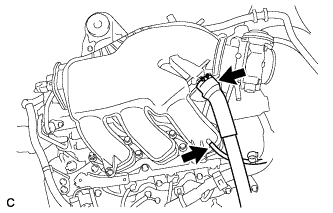
DISCONNECT VACUUM HOSE (for 1AR-FE)
-
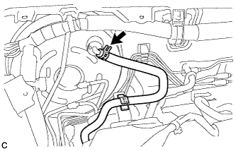
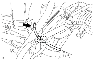
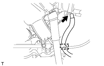
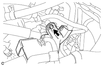
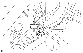
Slide the clip and disconnect the vacuum hose from the brake booster assembly.
-
-
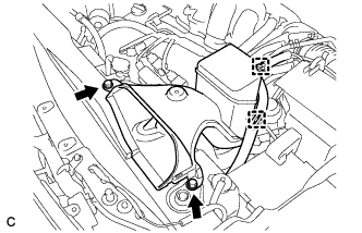
REMOVE VACUUM SWITCHING VALVE ASSEMBLY (for 1AR-FE)
-
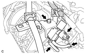
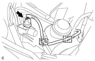
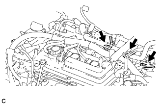
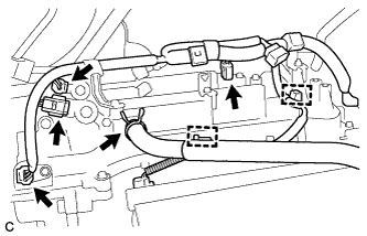
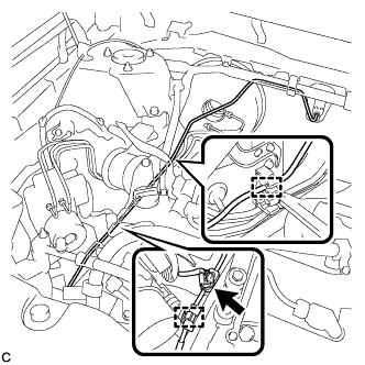
Disconnect the union to connector tube hose and wire harness clamp.
-
Disconnect the 2 vacuum hoses and connector.
-
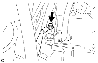
Remove the bolt and vacuum switching valve assembly.
-
-
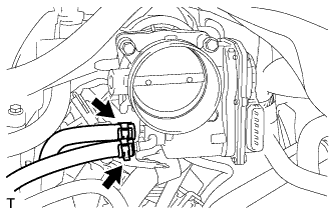
DISCONNECT VACUUM HOSE (for 2GR-FE)
-
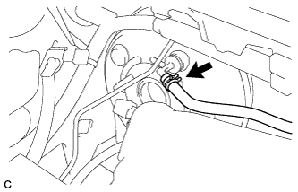
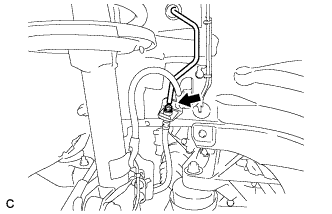
Slide the clip and disconnect the vacuum hose.
-
-
REMOVE BRAKE VACUUM CHECK VALVE ASSEMBLY
-
Remove the brake vacuum check valve assembly from the brake booster assembly.
-
-
REMOVE CHECK VALVE GROMMET
-
Remove the check valve grommet from the brake booster assembly.
-
-
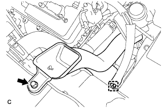
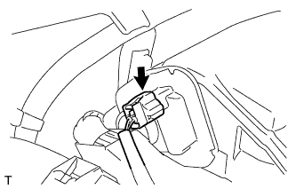
REMOVE BRAKE MASTER CYLINDER RESERVOIR ASSEMBLY
-
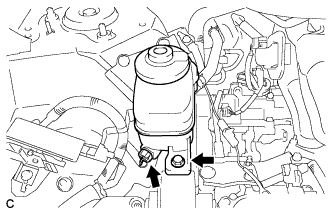
Disconnect the connector.
-
Remove the bolt and brake master cylinder reservoir assembly.
-
-
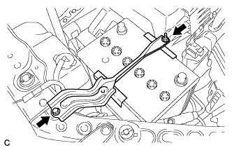
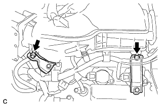
REMOVE RESERVOIR BRACKET
-
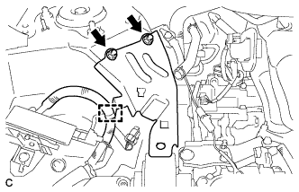
Disengage the clamp.
-
Remove the 2 nuts to remove the reservoir bracket.
-
-
DRAIN ENGINE COOLANT (for 2GR-FE)
-
Loosen the radiator drain cock plug and drain the coolant.
Note
Do not remove the radiator cap, cylinder block drain cock plugs and radiator drain cock plug while the engine and radiator are still hot. Pressurized, hot engine coolant and steam may be released and cause serious burns.
Tech Tips
Collect the coolant in a container and dispose of it according to the regulations in your area.
-
Remove the radiator cap from the radiator assembly.
-
Loosen the 2 cylinder block drain cock plugs.
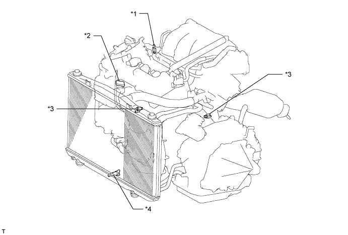
Text in Illustration *1 Air Drain Cock Plug *2 Radiator Cap *3 Cylinder Block Drain Cock Plug *4 Radiator Drain Cock Plug
-
-
REMOVE V-BANK COVER SUB-ASSEMBLY (for 2GR-FE)
-
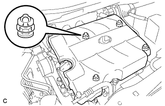
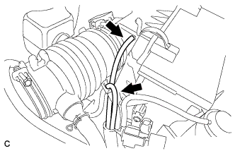
Hold the front of the V-bank cover sub-assembly and raise it to disengage the 2 retainers on the front of the V-bank cover sub-assembly. Continue to raise the V-bank cover sub-assembly to disengage the 2 retainers on the rear of the V-bank cover sub-assembly and remove the V-bank cover sub-assembly.
Note
Attempting to disengage both front and rear retainers at the same time may cause the V-bank cover sub-assembly to break.
-
-
REMOVE NO. 2 AIR CLEANER INLET (for 2GR-FE)
-
Disconnect the 2 vacuum hose clamps from the No. 2 air cleaner inlet.
-
Remove the 2 bolts and No. 2 air cleaner inlet.
-
-
REMOVE NO. 1 AIR CLEANER INLET (for 2GR-FE)
-
Disconnect the vacuum hose clamp from the No. 1 air cleaner inlet.
-
Remove the bolt and No. 1 air cleaner inlet.
-
-
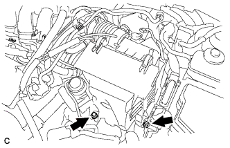
REMOVE BATTERY (for 2GR-FE)
-
Disconnect the positive (+) cable from the positive (+) battery terminal.
-
Loosen the nut, and remove the bolt from the battery clamp.
-
Remove the battery and battery tray.
-
-
REMOVE AIR CLEANER ASSEMBLY (for 2GR-FE)
-
Separate the mass air flow meter connector and wire harness clamp.
-
Separate the vacuum hose from the intake air surge tank assembly.
-
Separate the vacuum hose from the hose clamp.
-
Separate the vacuum switching valve connector and 2 wire harness clamps.
-
Separate the 2 vacuum hoses.
-
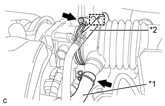
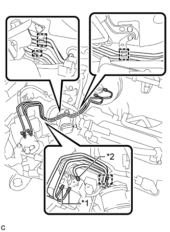
Text in Illustration *1 Ventilation Hose *2 Fuel Vapor Feed Hose Separate the ventilation hose and the fuel vapor feed hose.
-
Loosen the hose clamp and separate the air cleaner hose from the throttle body.
-
Remove the 2 bolts and remove the air cleaner assembly.
-
-
REMOVE INTAKE AIR SURGE TANK ASSEMBLY (for 2GR-FE)
-
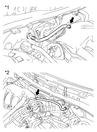
Text in Illustration *1 for RHD: *2 for LHD: Disconnect the union to check valve hose.
-
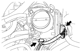
Disconnect the throttle body assembly connector and wire harness clamp.
-
Disconnect the vacuum hose clamp and fuel vapor feed hose.
-
Disconnect the 2 water by-pass hoses.
-
Disconnect the ventilation hose and vacuum hose.
-
Disconnect the connector from the intake air control valve assembly.
-
Remove the bolt and separate the No. 1 surge tank stay from the intake air surge tank assembly.
-
Remove the bolt and separate the throttle body bracket from the intake air surge tank assembly.
-
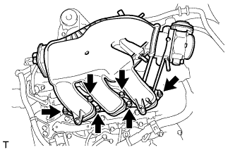
Remove the 2 nuts from the intake air surge tank assembly.
-
Using a 5 mm socket hexagon wrench, remove the 4 bolts.
-
Remove the intake air surge tank assembly and 3 air surge tank to intake manifold gaskets.
-
-
REMOVE NO. 1 SURGE TANK STAY (for 2GR-FE)
-
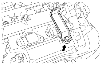
Remove the bolt and No. 1 surge tank stay.
-
-
REMOVE THROTTLE BODY BRACKET (for 2GR-FE)
-
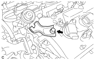
Remove the bolt and throttle body bracket.
-
-
REMOVE IGNITION COIL ASSEMBLY (for 2GR-FE)
-
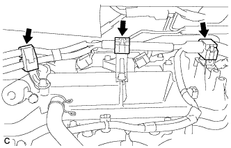
Disengage the 3 clamps.
-
Disconnect the 3 connectors.
-
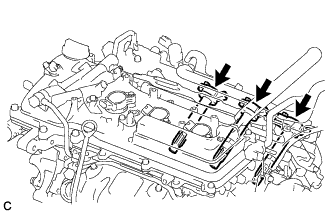
Remove the 3 bolts and 3 ignition coil assemblies (for Bank 1).
-
-
REMOVE NO. 2 TIMING GEAR COVER (for 2GR-FE)
-
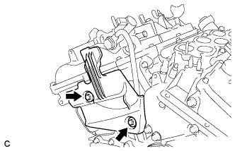
Remove the 2 bolts and No. 2 timing gear cover.
-
-
REMOVE OIL PIPE (for 2GR-FE)
-
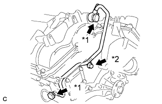
Text in Illustration *1 Oil Pipe Union *2 Bolt Remove the bolt.
-
Remove the 2 oil pipe unions and oil pipe.
-
Remove the oil control valve filter RH and gaskets.
-
-
SEPARATE ENGINE WIRE (for 2GR-FE)
-
Remove the bolt and separate the ground cable.
-
Disconnect the 4 connectors and ventilation hose, and disengage the 2 clamps from the cylinder head cover sub-assembly.
-
Remove the bolt and separate the wire harness protector.
-
-
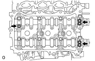
REMOVE CYLINDER HEAD COVER SUB-ASSEMBLY (for 2GR-FE)
-
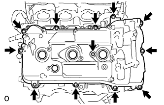
Remove the 12 bolts, seal washer, cylinder head cover sub-assembly and cylinder head cover gasket.
-
Remove the 3 gaskets.
-
-
SEPARATE WIRE HARNESS (for 1AR-FE)
-
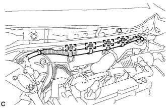
Disengage the 4 clamps and separate the wire harness.
-
-
SEPARATE SUCTION HOSE SUB-ASSEMBLY
-
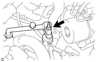
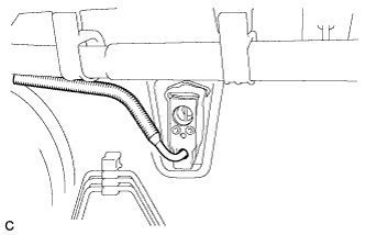
Remove the nut and separate the suction hose sub-assembly from the suction pipe sub-assembly.
-
Remove the O-ring from the suction hose sub-assembly.
Note
-
Seal the openings of the disconnected parts using vinyl tape to prevent entry of moisture and foreign matter.
-
Do not deform the piping.
-
-
-
REMOVE SUCTION PIPE SUB-ASSEMBLY
-
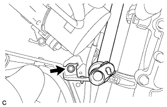
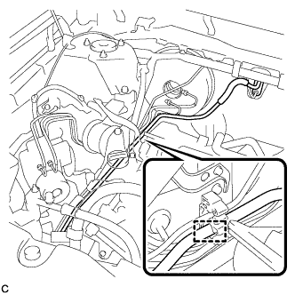
Remove the bolt and separate the suction pipe bracket from the brake actuator bracket.
-
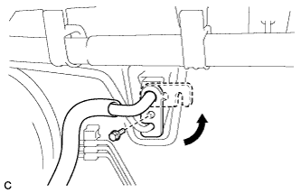
Remove the bolt and slide the hook connector.
-
Disengage the clamp.
-
Remove the suction pipe sub-assembly from the air conditioning unit.
-
Remove the O-ring from the suction pipe sub-assembly.
Note
-
Seal the openings of the disconnected parts using vinyl tape to prevent entry of moisture and foreign matter.
-
Do not deform the piping.
-
Do not damage the plastic clamp.
-
-
-
REMOVE AIR CONDITIONING TUBE AND ACCESSORY ASSEMBLY
-
Separate the air conditioning tube and accessory assembly from the air conditioning unit.
-
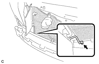
Remove the bolt and separate the air conditioning tube and accessory assembly from the cooler condenser assembly.
-
Disengage the 2 clamps, disconnect the connector and remove the air conditioning tube and accessory assembly.
-
Remove the 2 O-rings from the air conditioning tube and accessory assembly and air conditioning unit.
Note
-
Seal the openings of the disconnected parts using vinyl tape to prevent entry of moisture and foreign matter.
-
Do not deform the piping.
-
Do not damage the plastic clamp.
-
-
Remove the tube clamp.
-
-
REMOVE BRAKE LINE
-
Using a union nut wrench, disconnect the No. 8 front brake tube from the front flexible hose RH.
-
Text in Illustration *1 Front Brake Tube *2 No. 8 Front Brake Tube Using a union nut wrench, disconnect the front brake tube*1 and No. 8 front brake tube*2 from the brake actuator assembly.
-
Disengage the 5 clamps and separate the brake lines.
Note
-
Do not kink or damage the brake lines.
-
Do not allow any foreign matter such as dirt and dust to enter the brake lines.
-
-
-
REMOVE NO. 1 INSTRUMENT PANEL UNDER COVER SUB-ASSEMBLY
-
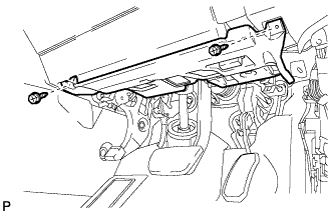
Remove the 2 screws <D>.
-
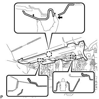
Disengage the claw and 2 guides as shown in the illustration.
-
Disconnect each connector.
-
Disengage each clamp and remove the No. 1 instrument panel under cover sub-assembly.
-
-
REMOVE BRAKE PEDAL RETURN SPRING
-
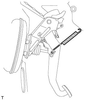
Remove the brake pedal return spring from the push rod pin and instrument panel reinforcement.
-
-
SEPARATE BRAKE MASTER CYLINDER PUSH ROD CLEVIS
-
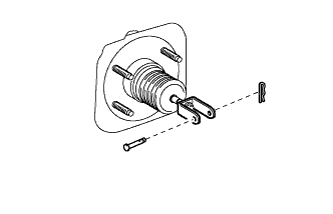
Remove the clip and push rod pin, and separate the brake master cylinder push rod clevis from the brake pedal sub-assembly.
-
-
REMOVE BRAKE MASTER CYLINDER PUSH ROD CLEVIS
-

Remove the 4 nuts and push out the brake booster assembly toward the engine room.
Note
Do not kink or damage the brake lines.
-
Loosen the lock nut and remove the brake master cylinder push rod clevis and lock nut.
-
-
REMOVE BRAKE BOOSTER ASSEMBLY
-
Remove the brake booster assembly from the body.
Note
Do not kink or damage the brake lines.
-
-
REMOVE BRAKE BOOSTER GASKET
-
Remove the brake booster gasket from the brake booster assembly.
-