BRAKE BOOSTER (for LHD) INSTALLATION

-
INSTALL BRAKE BOOSTER GASKET
-
Install a new brake booster gasket to the brake booster assembly.
-
-
INSTALL BRAKE MASTER CYLINDER PUSH ROD CLEVIS
-
Install the push rod clevis lock nut and brake master cylinder push rod clevis to the brake booster assembly, and temporarily tighten the push rod clevis lock nut.
Tech Tips
Fully tighten the lock nut after adjusting the brake pedal height.
-
-
INSTALL BRAKE BOOSTER ASSEMBLY
-
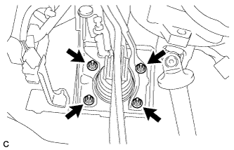
Install the brake booster assembly with the 4 nuts.
- Torque:
- 13 N*m { 130 kgf*cm, 9 ft.*lbf }
Note
Be careful not to damage the brake lines or clamps. If any parts are damaged, replace them with new ones.
-
-
CONNECT BRAKE MASTER CYLINDER PUSH ROD CLEVIS
-
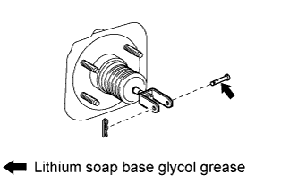
Apply lithium soap base glycol grease to the push rod pin.
-
Connect the brake master cylinder push rod clevis to the brake pedal with the push rod pin, and install a new clip as shown in the illustration.
-
-
INSTALL BRAKE PEDAL RETURN SPRING
-
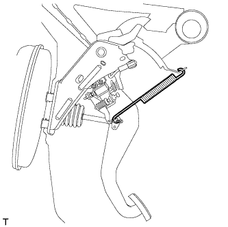
Install the brake pedal return spring between the instrument panel reinforcement and push rod pin.
-
-
INSTALL NO. 1 INSTRUMENT PANEL UNDER COVER SUB-ASSEMBLY
-
Engage each clamp.
-
Connect each connector.
-
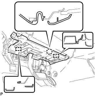
Engage the claw and 2 guides.
-
Install the No. 1 instrument panel under cover sub- assembly with the 2 screws <D>.
-
-
INSTALL NO. 1 FRONT BRAKE TUBE ASSEMBLY
-
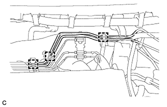
Engage the 3 clamps to install the No. 1 front brake tube assembly.
Note
Be careful not to damage the brake lines or clamps. If any parts are damaged, replace them with new ones.
-
-
INSTALL NO. 5 FRONT BRAKE TUBE
-
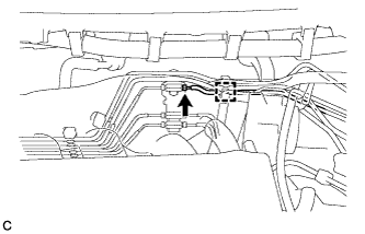
Engage the clamp to install the No. 5 front brake tube.
-
Using a union nut wrench, connect the No. 5 front brake tube.
- Torque:
- 15 N*m { 155 kgf*cm, 11 ft.*lbf }
Note
Use the formula to calculate special torque values for situations where the union nut wrench is combined with a torque wrench Click here.
-
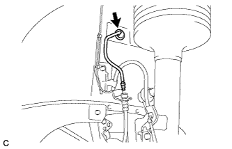
Engage the grommet of the No. 5 front brake tube.
-
Using a union nut wrench, connect the No. 5 front brake tube to the front brake flexible hose LH.
- Torque:
- 15 N*m { 155 kgf*cm, 11 ft.*lbf }
Note
Use the formula to calculate special torque values for situations where the union nut wrench is combined with a torque wrench Click here.
-
-
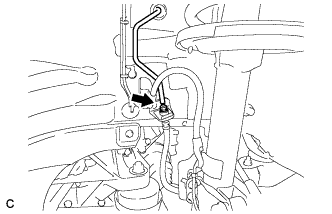
CONNECT FUEL VAPOR FEED HOSE
-
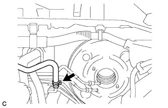
Connect the fuel vapor feed hose and slide the clip.
-
-
INSTALL CHECK VALVE GROMMET
-
Install a new check valve grommet to the brake booster assembly.
-
-
INSTALL BRAKE VACUUM CHECK VALVE ASSEMBLY
-
Install the brake vacuum check valve assembly to the brake booster assembly.
-
-
CONNECT VACUUM HOSE
-
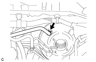
Connect the vacuum hose to the vacuum check valve and slide the clip.
-
for 1AR-FE:
-
Install the vacuum tube to the body with the 2 nuts.
- Torque:
- 5.4 N*m { 55 kgf*cm, 48 in.*lbf }
-
-
-
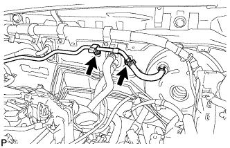
INSTALL ENGINE ROOM MAIN WIRE
-
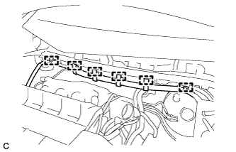
Engage the 6 clamps to install the engine room main wire.
-
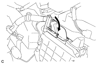
Connect the ECM connector and lower the lever.
Note
-
When connecting the connectors, make sure that dirt, water or other foreign matter does not become stuck between the connectors and other part.
-
Make sure that the lever is securely locked.
-
-
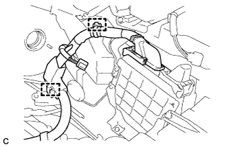
Engage the 2 clamps.
-
-
INSTALL BRAKE MASTER CYLINDER SUB-ASSEMBLY
-
INSPECT AND ADJUST BRAKE PEDAL