BRAKE MASTER CYLINDER (for LHD) INSTALLATION

-
INSPECT AND ADJUST BRAKE BOOSTER PUSH ROD
Note
Make an adjustment with no vacuum in the brake booster assembly. (Depress the brake pedal several times with the engine stopped.)
Tech Tips
-
Adjustment of the brake booster push rod is required when the brake master cylinder sub-assembly is replaced with a new one.
-
Adjustment is not necessary when the removed brake master cylinder sub-assembly is reused and the brake booster assembly is replaced with a new one.
-
Apply chalk to the tip of an accessory tool.
Tech Tips
The accessory tool is enclosed with a new brake master cylinder sub-assembly.
-
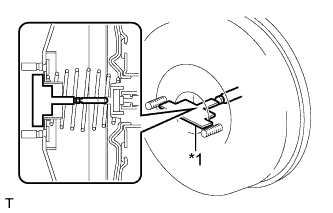
Text in Illustration *1 Accessory Tool Place the accessory tool on the brake booster assembly.
-
Measure the clearance between the brake booster push rod and accessory tool.
Standard clearance 0 mm (0 in.) Tech Tips
Adjust the clearance in the following cases:
-
If there is a clearance between the accessory tool and the shell of the brake booster (floating accessory tool), the push rod is protruding too far.
-
If the chalk does not stick on the tip of the brake booster push rod, the push rod protrusion is insufficient.
-
-
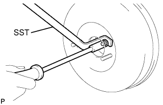
If the clearance is not as specified, adjust the push rod length by holding the rod using SST and turning the tip of the rod using a socket driver (7 mm).
- SST
- 09737-00020
Tech Tips
Check the push rod clearance again after adjustment.
-
-
INSTALL BRAKE MASTER CYLINDER SUB-ASSEMBLY
-
Install a new O-ring to the brake master cylinder sub-assembly.
-
Install the brake master cylinder sub-assembly to the brake booster assembly with the 2 nuts.
- Torque:
- 13 N*m { 127 kgf*cm, 9 ft.*lbf }
Note
-
The master cylinder requires careful handling. Do not allow the master cylinder to receive any impact, such as from being dropped. Do not reuse a master cylinder that has been dropped.
-
Do not strike or pinch the master cylinder piston, and do not cause any damage to the master cylinder piston by any other means.
-
When installing the master cylinder to the brake booster, or when removing the master cylinder from the brake booster, make sure that the master cylinder is kept horizontal or its tip faces downward (the piston faces upward) to prevent the master cylinder piston from falling out.
-
Do not allow any foreign matter to contaminate the master cylinder piston. If foreign matter gets on the piston, remove it by using a piece of cloth and then apply an even layer of lithium soap based glycol grease around the circumference (sliding part) of the piston.
-
Do not use any other type of grease or fluid.
-
-
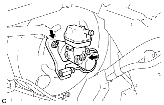
CONNECT BRAKE LINE
-
Using a union nut wrench, connect the 2 brake lines to the brake master cylinder sub-assembly.
- Torque:
- 20 N*m { 199 kgf*cm, 14 ft.*lbf }
Note
Use the formula to calculate special torque values for situations where the union nut wrench is combined with a torque wrench Click here.
-
-
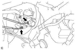
CONNECT NO. 1 RESERVOIR TUBE
-
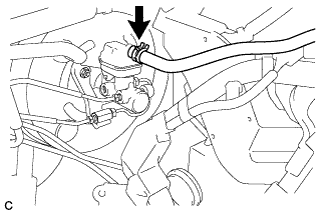
Connect the No. 1 reservoir tube to the brake master cylinder reservoir sub-assembly.
-
-
INSTALL AIR CLEANER ASSEMBLY (for 1AR-FE)
-

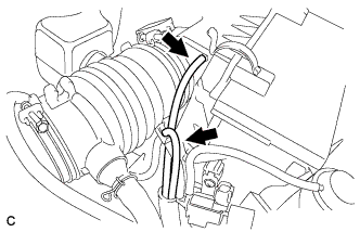
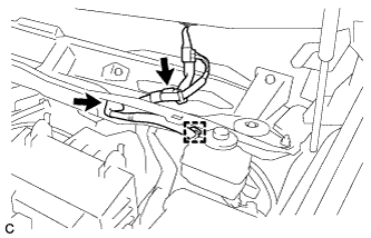
Text in Illustration *a A side view *b Front of the vehicle *c 11 to 14 mm (0.433 to 0.551 in.) Install the air cleaner hose with the hose clamp.
Note
Install the air cleaner hose clamp so that the orientation is as shown in the illustration.
-

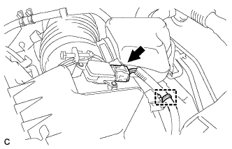
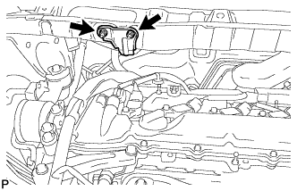
Text in Illustration *a Tab *b Hole Insert the tab of the air cleaner assembly to the hole of the vehicle body as shown in the illustration.
-
Install the air cleaner assembly with the 2 bolts.
- Torque:
- 5.5 N*m { 56 kgf*cm, 49 in.*lbf }
-

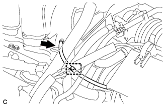
Text in Illustration *a Light blue paint mark Connect the vacuum hose to the 2 clamps of the air cleaner hose.
Note
Align the light blue paint mark of the vacuum hose with the clamp of the air cleaner hose.
-
Connect the vacuum hose.
-
Connect the ventilation hose to the cylinder head cover.
-
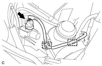
Connect the vacuum switching valve connector and install the vacuum hose to the 2 clamps.
-
Connect the No. 2 fuel vapor feed hose to the vacuum switching valve and clamp of the air cleaner hose.
-
Connect the mass air flow meter connector and install the wire harness clamp to the air cleaner assembly.
-
Connect the vacuum switching valve connector and install the wire harness clamp to the air cleaner assembly.
-
-
INSTALL BATTERY (for 1AR-FE)
-
Install the battery and battery tray.
-
Install the battery clamp with the bolt and nut.
- Torque:
- 5.4 N*m { 55 kgf*cm, 48 in.*lbf }
-
Connect the positive (+) cable to the positive (+) battery terminal.
- Torque:
- 6.4 N*m { 65 kgf*cm, 57 in.*lbf }
-
-
INSTALL NO. 1 AIR CLEANER INLET (for 1AR-FE)
-
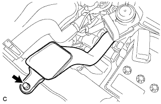
Install the No. 1 air cleaner inlet with the bolt.
- Torque:
- 8.0 N*m { 82 kgf*cm, 71 in.*lbf }
-
-
INSTALL NO. 2 AIR CLEANER INLET (for 1AR-FE)
-
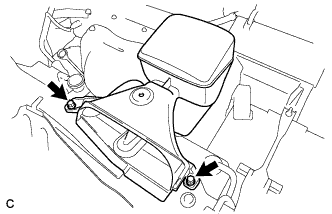
Install the No. 2 air cleaner inlet with the 2 bolts.
- Torque:
- 8.0 N*m { 82 kgf*cm, 71 in.*lbf }
-
-
INSTALL NO. 1 ENGINE COVER SUB-ASSEMBLY (for 1AR-FE)
-
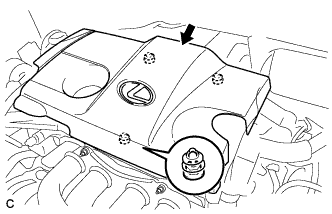
Fit the 3 retainers and install the No. 1 engine cover sub-assembly.
-
-
INSTALL AIR CLEANER ASSEMBLY (for 2GR-FE)
-
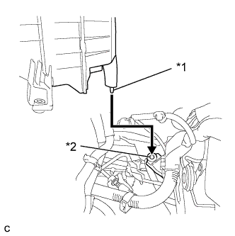
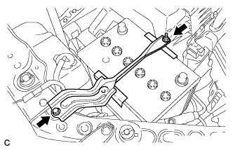
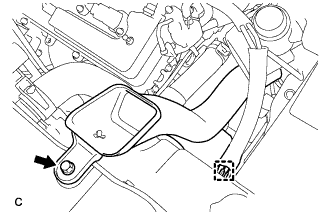
Text in Illustration *1 Tab *2 Hole Insert the tab of the air cleaner assembly to the hole of the vehicle body as shown in the illustration.
-
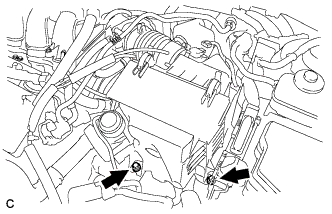
Install the air cleaner assembly with the 2 bolts.
- Torque:
- 5.5 N*m { 56 kgf*cm, 49 in.*lbf }
-
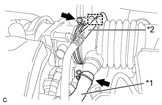
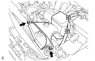
Text in Illustration *1 Ventilation Hose *2 Fuel Vapor Feed Hose Connect the air cleaner hose to the throttle body with the hose clamp.
-
Connect the ventilation hose and the fuel vapor feed hose.
-
Connect the 2 vacuum hoses.
-
Connect the 2 wire harness clamps and vacuum switching valve connector.
-
Connect the vacuum hose to the intake air surge tank assembly.
-
Install the hose to the hose clamp.
-
Connect the mass air flow meter connector and wire harness clamp.
-
-
INSTALL BATTERY (for 2GR-FE)
-
Install the battery and battery tray.
-
Install the battery clamp with the bolt and nut.
- Torque:
- 5.4 N*m { 55 kgf*cm, 48 in.*lbf }
-
Connect the positive (+) cable to the positive (+) battery terminal.
- Torque:
- 6.4 N*m { 65 kgf*cm, 57 in.*lbf }
-
-
INSTALL NO. 1 AIR CLEANER INLET (for 2GR-FE)
-
Install the No. 1 air cleaner inlet with the bolt.
- Torque:
- 8.0 N*m { 82 kgf*cm, 71 in.*lbf }
-
Connect the vacuum hose clamp to the No. 1 air cleaner inlet.
-
-
INSTALL NO. 2 AIR CLEANER INLET (for 2GR-FE)
-
Install the No. 2 air cleaner inlet with the 2 bolts.
- Torque:
- 8.0 N*m { 82 kgf*cm, 71 in.*lbf }
-
Connect the 2 vacuum hose clamps to the No. 2 air cleaner inlet.
-
-
INSTALL V-BANK COVER SUB-ASSEMBLY (for 2GR-FE)
-
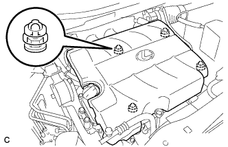
Fit the 4 retainers and install the V-bank cover sub-assembly.
-
-
CONNECT CABLE TO NEGATIVE BATTERY TERMINAL
Note
When disconnecting the cable, some systems need to be initialized after the cable is reconnected Click here.
-
BLEED BRAKE SYSTEM
-
INSTALL OUTER COWL TOP PANEL SUB-ASSEMBLY
-
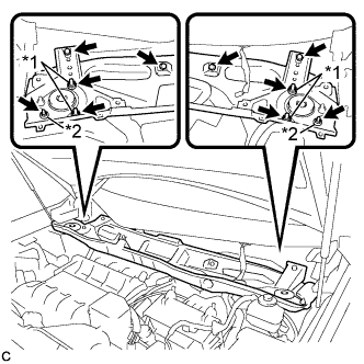
Install the outer cowl top panel sub-assembly with the 4 bolts, 4 nuts*1 and 2 nuts*2.
- Torque:
- Nut*1
- 85 N*m { 867 kgf*cm, 63 ft.*lbf }
- Nut*2
- 5.5 N*m { 56 kgf*cm, 49 in.*lbf }
- Bolt
- 5.5 N*m { 56 kgf*cm, 49 in.*lbf }
-
Engage the grommet and clamp to install the wire harness.
-
Connect the connector (w/ Windshield Deicer).
-
-
INSTALL HOSE BRACKET (for 1AR-FE)
-
Install the hose bracket to the outer cowl top panel sub-assembly with the 2 nuts.
- Torque:
- 9.0 N*m { 92 kgf*cm, 80 in.*lbf }
-
-
INSTALL FRONT SHOCK ABSORBER CAP LH (w/ Air Suspension)
-
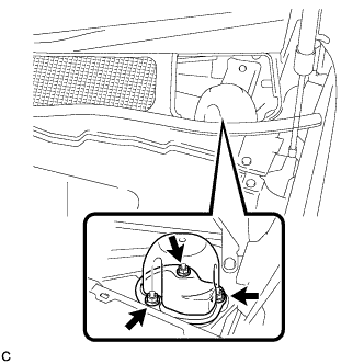
Install the front shock absorber cap with the 3 nuts.
- Torque:
- 14 N*m { 143 kgf*cm, 10 ft.*lbf }
-
-
INSTALL FRONT SHOCK ABSORBER CAP RH (w/ Air Suspension)
Tech Tips
Use the same procedure for the RH side and LH side.
-
INSTALL WINDSHIELD WIPER MOTOR AND LINK ASSEMBLY