BRAKE MASTER CYLINDER (for LHD) REMOVAL

Note
Make sure to release vacuum from the brake booster before removing the master cylinder from the brake booster.
-
PRECAUTION (w/ Air Suspension)
Note
Be sure to read Precaution thoroughly before servicing Click here.
-
PRECAUTION
Note
After the engine switch is turned off, the display and navigation module display (HDD navigation system) records various types of memory and settings. As a result, after turning the engine switch off, make sure to wait for the time specified in the following table before disconnecting the cable from the negative (-) battery terminal.
Waiting Time before Disconnecting Cable from Negative (-) Battery Terminal Specification Waiting Time w/o Telematics transceiver 60 sec. w/ Telematics transceiver 120 sec. -
DISCONNECT CABLE FROM NEGATIVE BATTERY TERMINAL
Note
When disconnecting the cable, some systems need to be initialized after the cable is reconnected Click here.
-
REMOVE WINDSHIELD WIPER MOTOR AND LINK ASSEMBLY
-
REMOVE FRONT SHOCK ABSORBER CAP LH (w/ Air Suspension)
-
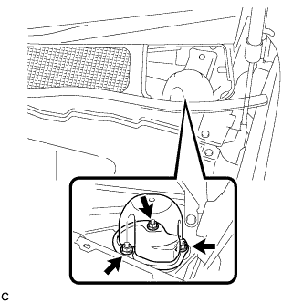
Remove the 3 nuts and the front shock absorber cap.
-
-
REMOVE FRONT SHOCK ABSORBER CAP RH (w/ Air Suspension)
Tech Tips
Use the same procedure for the RH side and LH side.
-
SEPARATE HOSE BRACKET (for 1AR-FE)
-
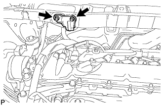
Remove the 2 nuts and separate the hose bracket from the outer cowl top panel sub-assembly.
-
-
REMOVE OUTER COWL TOP PANEL SUB-ASSEMBLY
-
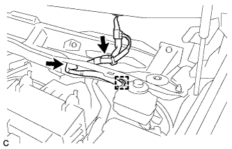
Disconnect the connector (w/ Windshield Deicer).
-
Disengage the grommet and clamp, and separate the wire harness.
-
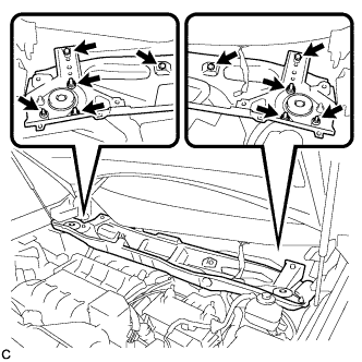
Remove the 6 nuts, 4 bolts and outer cowl top panel sub-assembly.
-
-
REMOVE NO. 1 ENGINE COVER SUB-ASSEMBLY (for 1AR-FE)
-
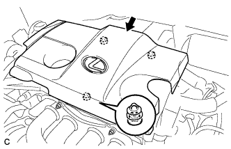
Lift the rear of the No. 1 engine cover sub-assembly to detach the cover from the 2 pins, and then lift the front of the No. 1 engine cover sub-assembly to detach the cover from the pin and remove the No. 1 engine cover sub-assembly.
Note
Attempting to disengage both front and rear clips at the same time may cause the No. 1 engine cover sub-assembly to break.
-
-
REMOVE NO. 2 AIR CLEANER INLET (for 1AR-FE)
-
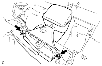
Remove the 2 bolts and No. 2 air cleaner inlet.
-
-
REMOVE NO. 1 AIR CLEANER INLET (for 1AR-FE)
-
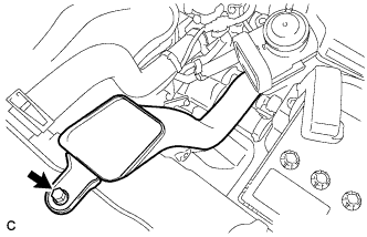
Remove the bolt and No. 1 air cleaner inlet.
-
-
REMOVE BATTERY (for 1AR-FE)
-
Disconnect the positive (+) cable from the positive (+) battery terminal.
-
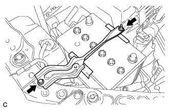
Loosen the nut, and remove the bolt from the battery clamp.
-
Remove the battery and battery tray.
-
-
REMOVE AIR CLEANER ASSEMBLY (for 1AR-FE)
-
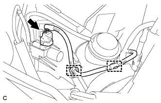
Disconnect the vacuum switching valve connector and fuel vapor feed hose.
-
Disconnect the mass air flow meter connector and separate the wire harness clamp from the air cleaner.
-
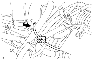
Disconnect the No. 2 fuel vapor feed hose from the vacuum switching valve and air cleaner hose.
-
Disconnect the vacuum switching valve connector and 2 wire harness clamps from the air cleaner.
-
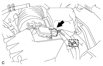
Disconnect the ventilation hose from the cylinder head cover.
-
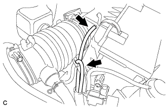
Disconnect the vacuum hose and separate it from the 2 hose clamps of the air cleaner hose.
-
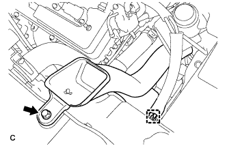
Loosen the bolt of the hose clamp and disconnect the air cleaner hose from the throttle body assembly.
-
Remove the 2 bolts and move the air cleaner assembly upward to disengage and remove it from the throttle body assembly.
-
-
REMOVE V-BANK COVER SUB-ASSEMBLY (for 2GR-FE)
-
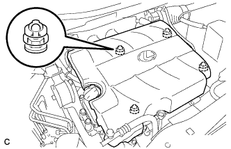
Hold the front of the V-bank cover sub-assembly and raise it to disengage the 2 retainers on the front of the V-bank cover sub-assembly. Continue to raise the V-bank cover sub-assembly to disengage the 2 retainers on the rear of the V-bank cover sub-assembly and remove the V-bank cover sub-assembly.
Note
Attempting to disengage both front and rear retainers at the same time may cause the V-bank cover sub-assembly to break.
-
-
REMOVE NO. 2 AIR CLEANER INLET (for 2GR-FE)
-
Disconnect the 2 vacuum hose clamps from the No. 2 air cleaner inlet.
-
Remove the 2 bolts and No. 2 air cleaner inlet.
-
-
REMOVE NO. 1 AIR CLEANER INLET (for 2GR-FE)
-
Disconnect the vacuum hose clamp from the No. 1 air cleaner inlet.
-
Remove the bolt and No. 1 air cleaner inlet.
-
-
REMOVE BATTERY (for 2GR-FE)
-
Disconnect the positive (+) cable from the positive (+) battery terminal.
-
Loosen the nut, and remove the bolt from the battery clamp.
-
Remove the battery and battery tray.
-
-
REMOVE AIR CLEANER ASSEMBLY (for 2GR-FE)
-
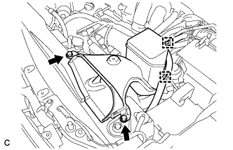
Separate the mass air flow meter connector and wire harness clamp.
-
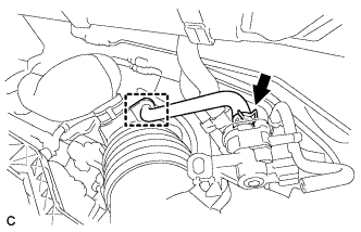
Separate the vacuum hose from the intake air surge tank assembly.
-
Separate the vacuum hose from the hose clamp.
-
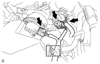
Separate the vacuum switching valve connector and 2 wire harness clamps.
-
Separate the 2 vacuum hoses.
-
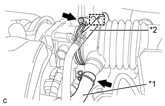
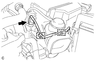
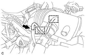
Text in Illustration *1 Ventilation Hose *2 Fuel Vapor Feed Hose Separate the ventilation hose and the fuel vapor feed hose.
-
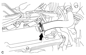
Loosen the hose clamp and separate the air cleaner hose from the throttle body.
-
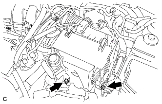
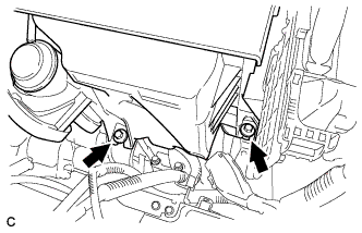
Remove the 2 bolts and remove the air cleaner assembly.
-
-
DRAIN BRAKE FLUID
Note
If brake fluid leaks onto any painted surface, immediately wash it off.
-
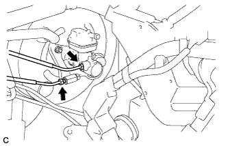
DISCONNECT NO. 1 RESERVOIR TUBE
-
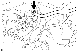
Slide the clip and disconnect the No. 1 reservoir tube from the brake master cylinder reservoir sub-assembly.
-
-
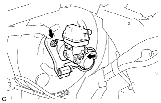
DISCONNECT BRAKE LINE
-
Using a union nut wrench, disconnect the 2 brake lines from the brake master cylinder sub-assembly.
-
-
REMOVE BRAKE MASTER CYLINDER SUB-ASSEMBLY
-
Remove the 2 nuts and brake master cylinder sub-assembly.
Note
-
The master cylinder requires careful handling. Do not allow the master cylinder to receive any impact, such as from being dropped. Do not reuse a master cylinder that has been dropped.
-
Do not strike or pinch the master cylinder piston, and do not cause any damage to the master cylinder piston by any other means.
-
Make sure to release vacuum from the brake booster before removing the master cylinder from the brake booster.
-
When installing the master cylinder to the brake booster, or when removing the master cylinder from the brake booster, make sure that the master cylinder is kept horizontal or its tip faces downward (the piston faces upward) to prevent the master cylinder piston from falling out.
-
Do not allow any foreign matter to contaminate the master cylinder piston. If foreign matter gets on the piston, remove it by using a piece of cloth and then apply an even layer of lithium soap base glycol grease around the circumference (sliding part) of the piston.
-
Do not use any other type of grease or fluid.
-
-
Remove the O-ring from the brake master cylinder sub-assembly.
-