-
Use the same procedure for the RH side and LH side.
-
The following procedure is for the LH side.
-
The rear speed sensor is a component of the rear axle hub and bearing assembly. If the sensor malfunctions, replace the rear axle hub and bearing assembly.
-
If the sensor rotor needs to be replaced, replace it together with the rear axle hub and bearing assembly.
- Click here
INSTALL REAR AXLE HUB AND BEARING ASSEMBLY
-
Install the rear axle hub and bearing assembly (Click here).
Tip:
-
The rear speed sensor is a component of the rear axle hub and bearing assembly. If the sensor malfunctions, replace the rear axle hub and bearing assembly.
-
If the sensor rotor needs to be replaced, replace it together with the rear axle hub and bearing assembly.
-
-
- Click here
INSPECT REAR AXLE HUB BEARING LOOSENESS
-
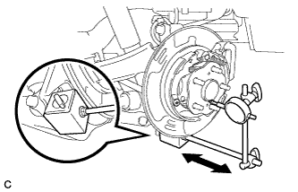
Using a dial indicator, check for looseness near the center of the rear axle hub.
Maximum looseness 0 mm (0 in.) Note:
-
Ensure that the dial indicator is set perpendicular to the measurement surface.
-
Keep the magnet of the dial indicator away from the rear axle hub and bearing assembly.
Tip:If the looseness exceeds the maximum, replace the rear axle hub and bearing assembly.
-
-
- Click here
INSPECT REAR AXLE HUB RUNOUT
-
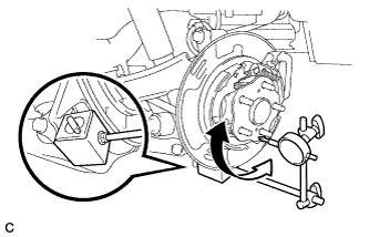
Using a dial indicator, check for runout on the surface of the rear axle hub outside the rear axle hub bolt.
Maximum runout 0.08 mm (0.00314 in.) Note:
-
Ensure that the dial indicator is set perpendicular to the measurement surface.
-
Keep the magnet of the dial indicator away from the rear axle hub and bearing assembly.
Tip:If the runout exceeds the maximum, replace the rear axle hub and bearing assembly.
-
-
- Click here
INSTALL REAR DISC
-
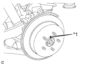
Align the matchmarks and install the rear disc.
Table 1. Text in Illustration *1 Matchmark Note:When replacing the rear disc with a new one, select the installation position where the rear disc has minimal runout.
-
- Click here
INSTALL REAR DISC BRAKE CALIPER ASSEMBLY
-
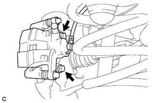
Install the rear disc brake caliper assembly with the 2 bolts.
78 N*m 799 kgf*cm 58 ft.*lbf
-
- Click here
INSTALL REAR SPEED SENSOR WIRE
-
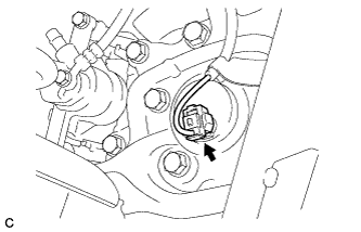
Connect the connector to the rear speed sensor.
-
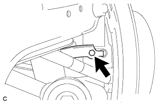
Install the No. 1 bracket with the bolt.
8.0 N*m 82 kgf*cm 71 in.*lbf
-
- Click here
INSTALL REAR SUSPENSION ARM COVER
-
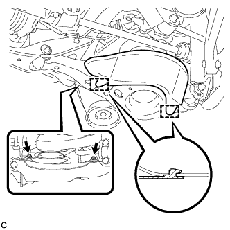
Install the rear suspension arm cover to the rear No. 2 suspension arm assembly with the 2 bolts as shown in the illustration.
12 N*m 122 kgf*cm 9 ft.*lbf
-
- Click here
INSTALL REAR WHEEL
103 N*m 1050 kgf*cm 76 ft.*lbf - Click here
CONNECT CABLE TO NEGATIVE BATTERY TERMINAL
Note:When disconnecting the cable, some systems need to be initialized after the cable is reconnected (Click here).
- Click here
INSPECT AND ADJUST REAR WHEEL ALIGNMENT
- Click here
CHECK FOR SPEED SENSOR SIGNAL