TIRE PRESSURE WARNING VALVE INSTALLATION

Note
-
Always use a new grommet and valve core when installing the tire pressure warning valve and transmitter.
-
Check that the washer and nut are not damaged, and replace them if necessary.
-
Make sure not to damage the urethane covered backside of the tire pressure warning valve and transmitter (the surface opposite to the side with the ID code) with anything sharp.
-
Write down the ID number before installation.
-
Check that there is no oil, water or lubricant around the rim hole, tire pressure warning valve and transmitter, washer and nut. Failing to do so may result in improper installation.
-
Use only a specified tire valve cap. If an unspecified tire valve cap is used, it may seize to the tire pressure warning valve and transmitter.
-
INSTALL TIRE PRESSURE WARNING VALVE AND TRANSMITTER
-
Install a new grommet to the tire pressure warning valve and transmitter.
Note
A new tire pressure warning valve and transmitter comes with a grommet installed. Make sure not to install an extra grommet.
-
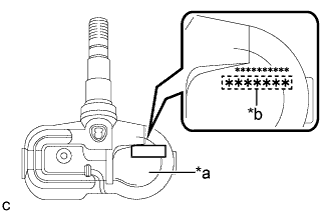
Text in Illustration *a Printed Surface *b 7-digit Transmitter ID Number Write down the 7-digit transmitter ID number as shown in the illustration.
-
Insert the tire pressure warning valve and transmitter with grommet from the inside of the rim.
Note
-
Make sure that the tire pressure warning valve and transmitter is installed so that the printed surface can be seen. If the tire pressure warning valve and transmitter is installed upside down, it may be damaged or fail to transmit signals when driving at high speeds.
-
Check that there is no deformation or damage to the tire pressure warning valve and transmitter.
-
Check that there is no foreign matter on the grommet and around the rim hole.
-
-
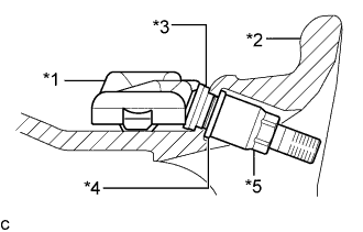
Text in Illustration *1 Tire Pressure Warning Valve and Transmitter *2 Rim *3 Grommet *4 Washer *5 Nut From the outside of the rim, install the washer onto the tire pressure warning valve and transmitter, and tighten the nut.
- Torque:
- 4.0 N*m { 41 kgf*cm, 35 in.*lbf }
Note
-
No further tightening is required once the nut is tightened to the specified torque.
-
Check that there is no foreign matter on the grommet, washer and nut.
-
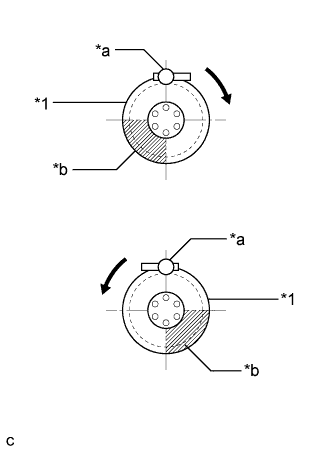
Text in Illustration *1 Rim *a Mount Tool of the Mounting Machine *b Area for Tire Pressure Warning Valve and Transmitter 
Rim Rotating Direction Set the tire and disc wheel onto the mounting machine.
Note
-
Position the main body of the tire pressure warning valve and transmitter in the area shown in the illustration.
-
If the tire pressure warning valve and transmitter is positioned outside this area, it will interfere with the tire bead and may be damaged.
-
-
Apply a sufficient coat of soapy water or equivalent to the tire bead and rim.
Note
Do not apply soapy water or equivalent directly to the tire pressure warning valve and transmitter.
-
Using a mounting machine, install the tire to the disc wheel.
Note
-
Make sure that the tire bead and mount tool do not interfere with the tire pressure warning valve and transmitter.
-
Make sure that the tire pressure warning valve and transmitter is not clamped by the bead and rim.
-
-
Install a new valve core.
-
Retighten the nut to the specified torque.
- Torque:
- 4.0 N*m { 41 kgf*cm, 35 in.*lbf }
Note
No further tightening is required once the nut is tightened to the specified torque.
-
Check the surroundings of the tire pressure warning valve and transmitter for air leaks with soapy water or equivalent.
-
If air is leaking from the valve core, press the valve core several times to remove foreign matter. Replace the valve core as necessary.
-
If air is leaking from around the tire pressure warning valve and transmitter, check if the grommet, washer and nut are not deformed, damaged or contaminated with foreign matter. Replace the grommet, washer or nut as necessary.
-
-
Install the tire valve cap.
-
-
INSTALL WHEEL ASSEMBLY
- Torque:
- 103 N*m { 1050 kgf*cm, 76 ft.*lbf }
-
INSPECT TIRES
-
Check the tires for wear and proper inflation pressure.
Cold Tire Inflation Pressure Tire Size Front
kPa (kgf/cm2, psi)
Rear
kPa (kgf/cm2, psi)
235/60R18 103V 220 (2.2, 32)*1
240 (2.4, 35)*2
220 (2.2, 32)*1
260 (2.6, 38)*2
235/55R19 101V 220 (2.2, 32)*1
250 (2.5, 36)*2
220 (2.2, 32)*1
280 (2.8, 41)*2
*1: For driving under 160 km/h (100 mph)
*2: For driving at over 160 km/h (100 mph)
-
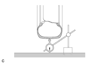
Using a dial indicator, check the runout of the tires.
Maximum Tire Runout 1.4 mm (0.0551 in.) or less
-
-
REGISTER TRANSMITTER ID
-
INSPECT TIRE PRESSURE WARNING SYSTEM
-
PERFORM INITIALIZATION