WIPER SWITCH REMOVAL

-
PRECAUTION (w/ Navigation System for HDD)
Note
After the engine switch is turned off, the display and navigation module display (HDD navigation system) records various types of memory and settings. As a result, after turning the engine switch off, make sure to wait for the time specified in the following table before disconnecting the cable from the negative (-) battery terminal.
Waiting Time before Disconnecting Cable from Negative (-) Battery Terminal Specification Waiting Time w/o Telematics transceiver 60 sec. w/ Telematics transceiver 120 sec. -
REMOVE STEERING COLUMN COVER
-
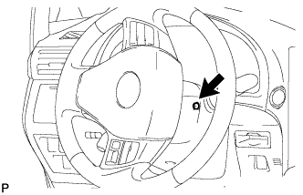
Turn the steering wheel assembly to the right and remove the screw as shown in the illustration.
-
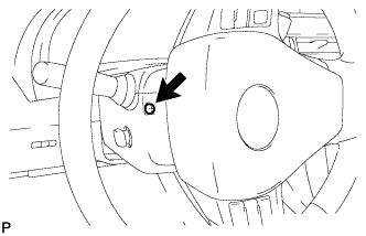
Turn the steering wheel assembly to the left and remove the screw as shown in the illustration.
-
Disable the auto tilt away function by changing the customize parameter Click here.
Note
Record the current customize parameter setting (whether the auto tilt away function is enabled or disabled) in order to restore the current setting after finishing this operation.
Tech Tips
Performing the above operation disables the auto tilt away function when the engine switch is turned off.
-
Turn the engine switch on (IG). Operate the tilt and telescopic switch to fully extend and upper the steering column assembly.
-
Turn the engine switch off and disconnect the cable from the negative (-) battery terminal.
Note
When disconnecting the cable, some systems need to be initialized after the cable is reconnected Click here.
-
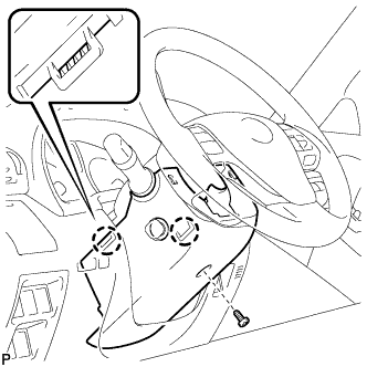
Remove the screw.
-
Disengage the 2 claws and remove the lower steering column cover.
Note
Do not damage the tilt and telescopic switch.
-
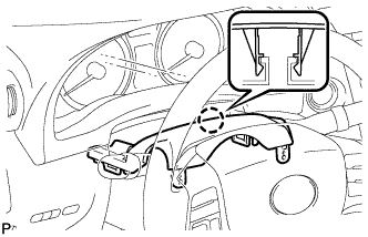
Disengage the claw.
-
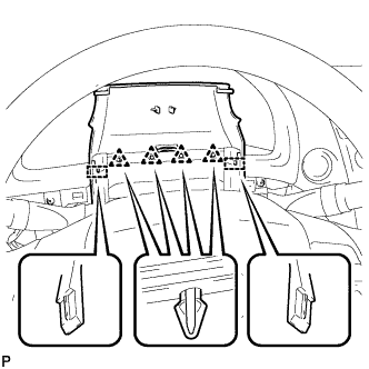
Disengage the 4 clips and 2 guides to remove the upper steering column cover as shown in the illustration.
-
-
REMOVE WINDSHIELD WIPER SWITCH ASSEMBLY
-
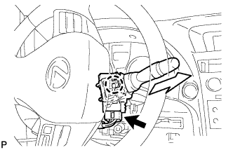
Disconnect the connector.
-
Disengage the claw and remove the windshield wiper switch assembly as shown in the illustration.
Note
If the claw is pushed with excessive force, it may break.
-