REAR LOWER ARM REMOVAL

Tech Tips
-
Use the same procedure for the RH side and LH side.
-
The procedure listed below is for the LH side.
-
PRECAUTION (w/ Air Suspension)
-
REMOVE REAR WHEEL
-
REMOVE REAR SUSPENSION ARM COVER (w/o Air Suspension)
-
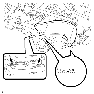
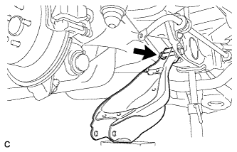
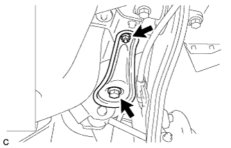
Remove the 2 bolts and rear suspension arm cover from the rear No. 2 suspension arm assembly.
-
-
REMOVE REAR SUSPENSION ARM COVER (w/ Air Suspension)
-
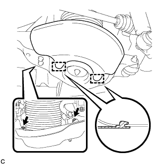
Remove the 2 bolts and rear suspension arm cover from the rear No. 2 suspension arm assembly.
-
-
REMOVE REAR STABILIZER LINK SUB-ASSEMBLY
-
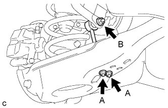
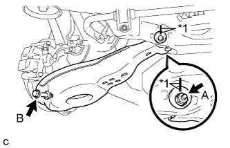
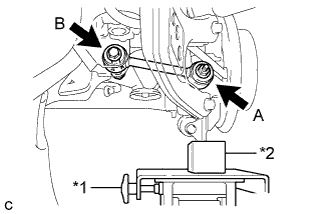
Remove the 2 nuts (A) and rear stabilizer link sub-assembly from the rear No. 2 suspension arm assembly.
-
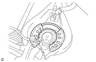
Remove the nut (B) and separate the rear stabilizer link sub-assembly from the rear stabilizer bar.
Tech Tips
If the ball joint turns together with the nut (B), use a hexagon wrench (6 mm) to hold the stud bolt.
-
-
REMOVE REAR PNEUMATIC CYLINDER ASSEMBLY (w/ Air Suspension)
-
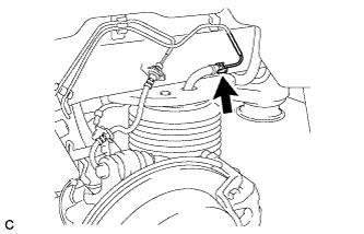
Disconnect the air tube from the rear pneumatic cylinder assembly.
Tech Tips
For the disconnecting procedure of the tube (type 2), refer to Precaution of Suspension Control System Click here.
-
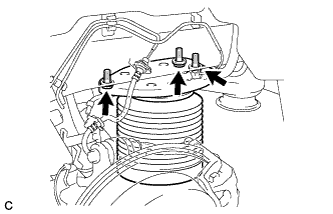
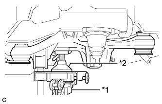
Remove the 3 bolts and separate the rear pneumatic cylinder assembly from the body.
-
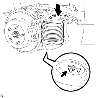
Compress the rear pneumatic cylinder assembly as shown in the illustration.
-
Remove the bolt and rear pneumatic cylinder assembly from the rear No. 2 suspension arm assembly.
Note
-
Hold the lower part of the rear pneumatic cylinder assembly when removing it.
-
Do not extend the rear pneumatic cylinder assembly when removing it.
-
-
Remove the 2 O-rings, plate and No. 2 connector from the rear pneumatic cylinder assembly.
Note
Perform this procedure when reusing the rear pneumatic cylinder assembly.
Tech Tips
For the removing procedure of the tube (type 2), refer to Precaution of Suspension Control System Click here.
-
-
REMOVE REAR NO. 2 SUSPENSION ARM ASSEMBLY (w/o Air Suspension)
-
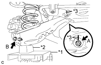
Text in Illustration *1 Jack *2 Wooden Block *3 Matchmark Put matchmarks on the adjust cams and the rear suspension member sub-assembly.
-
Using a jack and wooden block, jack up the rear No. 2 suspension arm assembly to replicate standard vehicle height conditions.
CAUTION:
Do not jack up the rear No. 2 suspension arm assembly too high as the vehicle may fall.
-
Loosen the nut (A).
Note
When loosening the nut (A), keep the toe adjust cam from rotating.
-
Remove the bolt (B) and nut, and separate the rear No. 2 suspension arm assembly from the rear axle carrier sub-assembly.
Note
Since the stopper nut is used, loosen the bolt (B).
-
Slowly lower the rear No. 2 suspension arm assembly, and remove the rear coil spring.
-
Remove the rear lower coil spring insulator from the rear No. 2 suspension arm assembly.
-
Remove the nut, No. 2 camber adjust cam, rear suspension toe adjust cam sub-assembly and rear No. 2 suspension arm assembly.
Note
When removing the nut, keep the toe adjust cam from rotating.
-
-
REMOVE REAR NO. 2 SUSPENSION ARM ASSEMBLY (w/ Air Suspension)
-
Remove the rear spring set plate from the rear No. 2 suspension arm assembly.
-
Text in Illustration *1 Matchmark Put matchmarks on the adjust cams and the rear suspension member sub-assembly.
-
Remove the bolt (B) and nut.
Note
Since the stopper nut is used, loosen the bolt (B).
-
Remove the nut (A), No. 2 camber adjust cam, rear suspension toe adjust cam sub-assembly and rear No. 2 suspension arm assembly.
Note
When removing the nut (A), keep the toe adjust cam from rotating.
-
-
REMOVE REAR NO. 1 SUSPENSION ARM ASSEMBLY (for 2WD)
-
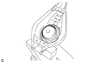
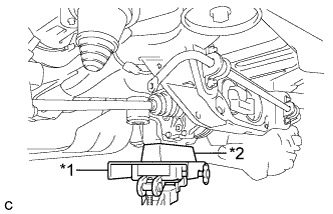
Text in Illustration *1 Jack *2 Attachment Support the rear suspension member with a jack using an attachment or an equivalent tool as shown in the illustration.
Note
Keep supporting the rear suspension member until the installation of the rear No. 1 suspension arm assembly has been completed.
-
Remove the bolt, nut and rear lower suspension member stopper.
-
Text in Illustration *1 Jack *2 Wooden Block Using a jack and wooden block, jack up the rear axle assembly to replicate standard vehicle height conditions.
-
Remove the nut (A) and spacer.
-
Remove the bolt (B), nut and rear No. 1 suspension arm assembly.
Note
Since the stopper nut is used, loosen the bolt (B).
-
Slowly lower the rear axle assembly.
-
-
REMOVE REAR NO. 1 SUSPENSION ARM ASSEMBLY (for AWD)
-
Text in Illustration *1 Jack *2 Wooden Block Support the rear differential carrier assembly with a jack using a wooden block as shown in the illustration.
Note
Keep supporting the rear differential carrier assembly until the installation of the rear No. 1 suspension arm assembly has been completed.
-
Remove the bolt, nut and rear lower suspension member stopper.
-
Text in Illustration *1 Jack *2 Wooden Block Using a jack and wooden block, jack up the rear axle assembly to replicate standard vehicle height conditions.
-
Remove the nut (A) and spacer.
-
Remove the bolt (B), nut and rear No. 1 suspension arm assembly.
Note
Since the stopper nut is used, loosen the bolt (B).
-
Slowly lower the rear axle assembly.
-