FRONT SHOCK ABSORBER (w/ Air Suspension) INSTALLATION

Tech Tips
-
Use the same procedure for the RH side and LH side.
-
The procedure listed below is for the LH side.
-
INSTALL FRONT PNEUMATIC CYLINDER INNER COVER
-
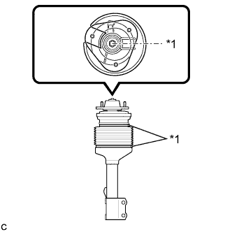
Text in Illustration *1 Fixed Point of Clamping Joint Install the front pneumatic cylinder inner cover to the front pneumatic with shock absorber cylinder sub-assembly with 2 new height control cover bands.
-
Cut the surplus of height control cover bands.
-
-
INSTALL NO. 4 HEIGHT CONTROL TUBE O-RING
Tech Tips
It is unnecessary to perform the following procedures if the front pneumatic with shock absorber cylinder assembly has been replaced with a new one.
-
Lightly coat 2 new O-rings with MP grease No. 2.
-

Text in Illustration *1 O-Ring Install the 2 new O-rings to the No. 4 height control tube straight tube or equivalent as shown in the illustration.
-
-
INSPECT HEIGHT CONTROL TUBE COVER CUSHION
-
Visually check the height control tube cover cushion from above.
OK The height control tube cover cushion is not cracked, pinched or misaligned. If any abnormality is found, replace the height control tube cover cushion with a new one.
-
-
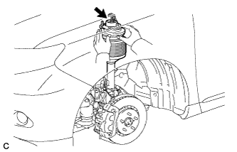
INSTALL FRONT PNEUMATIC WITH SHOCK ABSORBER CYLINDER ASSEMBLY
-
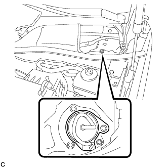
Temporarily install the front pneumatic with shock absorber cylinder assembly (upper side) with the 3 nuts.
-
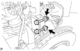
Install the front shock absorber with coil spring (lower side) to the steering knuckle and insert the 2 bolts and 2 nuts.
- Torque:
- 290 N*m { 2957 kgf*cm, 214 ft.*lbf }
Note
When installing the nuts, keep the bolts from rotating.
-
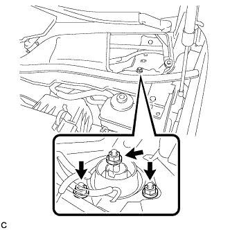
Fully tighten the front pneumatic with shock absorber cylinder assembly (upper side) with the 3 nuts.
- Torque:
- 85 N*m { 867 kgf*cm, 63 ft.*lbf }
-
Install the height control clamp to the front pneumatic with shock absorber cylinder assembly.
-
-
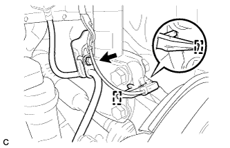
CONNECT NO. 4 HEIGHT CONTROL TUBE
-
Install the No. 4 height control tube and height control tube clamp to the front pneumatic with shock absorber cylinder assembly.
Note
Make sure to hold the front pneumatic with shock absorber cylinder chamber by hand.
-
Tighten the lock nut.
- Torque:
- 17 N*m { 175 kgf*cm, 13 ft.*lbf }
Note
Keep the chamber of the front pneumatic with shock absorber cylinder assembly unmoved by holding it by hand.
Tech Tips
For the connecting procedure of the tube (Type 1), refer to the Precaution of Suspension Control System Click here.
-
-
INSTALL FRONT STABILIZER LINK ASSEMBLY
-
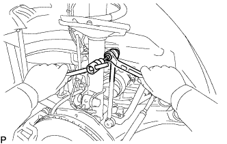
Install the front stabilizer link assembly to the front shock absorber with the nut.
- Torque:
- 74 N*m { 755 kgf*cm, 55 ft.*lbf }
Tech Tips
If the ball joint turns together with the nut, use a hexagon wrench (6 mm) to hold the stud bolt.
-
-
INSTALL FRONT SPEED SENSOR
-
Install the front speed sensor and front flexible hose with the bolt.
- Torque:
- 19 N*m { 194 kgf*cm, 14 ft.*lbf }
Note
Do not twist the front speed sensor when installing it.
-
Install the clamp.
-
-
INSTALL FRONT WHEEL
- Torque:
- 103 N*m { 1050 kgf*cm, 76 ft.*lbf }
-
INSPECT FOR AIR LEAK
-
Inspect for air leaks Click here.
-
-
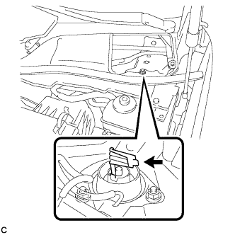
INSTALL FRONT SHOCK ABSORBER CAP
-
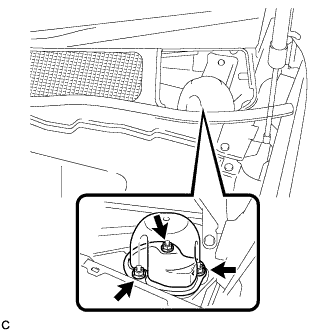
Install the front shock absorber cap with the 3 nuts.
- Torque:
- 14 N*m { 143 kgf*cm, 10 ft.*lbf }
-
-
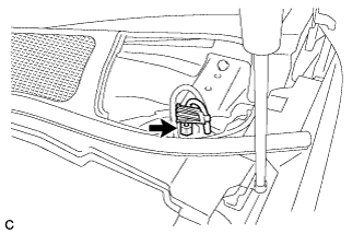
INSTALL COWL TOP SILENCER PAD
-
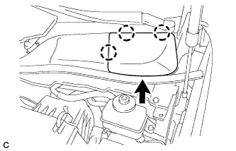
Engage the 3 claws to install the cowl top silencer pad.
-
-
ADJUST VEHICLE HEIGHT
-
Adjust the vehicle height Click here.
-
-
INSPECT AND ADJUST FRONT WHEEL ALIGNMENT
-
Inspect and adjust the front wheel alignment Click here.
-