REAR SUSPENSION MEMBER (for AWD) REMOVAL

-
PRECAUTION (w/ Air Suspension)
-
PRECAUTION (w/ Navigation System for HDD)
Note
After the engine switch is turned off, the display and navigation module display (HDD navigation system) records various types of memory and settings. As a result, after turning the engine switch off, make sure to wait for the time specified in the following table before disconnecting the cable from the negative (-) battery terminal.
Waiting Time before Disconnecting Cable from Negative (-) Battery Terminal Specification Waiting Time w/o Telematics transceiver 60 sec. w/ Telematics transceiver 120 sec. -
DISCONNECT CABLE FROM NEGATIVE BATTERY TERMINAL (w/ Air Suspension)
Note
When disconnecting the cable, some systems need to be initialized after the cable is reconnected Click here.
-
REMOVE REAR WHEELS
-
DRAIN BRAKE FLUID
-
DRAIN DIFFERENTIAL OIL
-
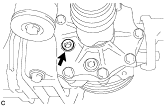
Using a hexagon wrench (10 mm), remove the differential inspection plug and gasket.
-
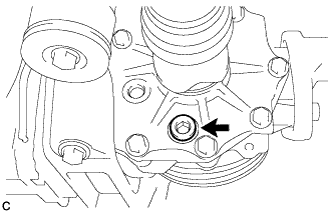
Using a hexagon wrench (10 mm), remove the rear differential drain plug and gasket to drain the differential oil.
-
Using a hexagon wrench (10 mm), install the rear differential drain plug with a new gasket.
- Torque:
- 39 N*m { 398 kgf*cm, 29 ft.*lbf }
-
Using a hexagon wrench (10 mm), temporarily install the differential inspection plug.
Tech Tips
Add differential oil before installing a new gasket and fully tightening the differential inspection plug.
-
-
REMOVE TAIL EXHAUST PIPE ASSEMBLY
-
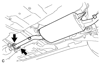
Remove the 2 bolts and 2 compression springs.
-
Remove the tail exhaust pipe assembly from the 4 exhaust pipe supports.
-
Remove the gasket from the center exhaust pipe assembly.
-
-
REMOVE PROPELLER WITH CENTER BEARING SHAFT ASSEMBLY
-
Depress the brake pedal and hold it.
-
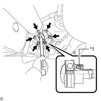
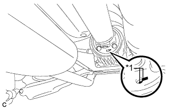
Text in Illustration *1 Piece of Cloth Using a hexagon wrench (6 mm), loosen the cross groove joint set bolts 1/2 turn.
Note
-
Put a piece of cloth or equivalent into the inside of the universal joint cover so that the boot does not touch the inside of the universal joint cover.
-
Do not remove the bolts.
-
-
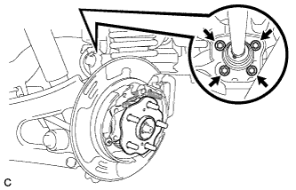
Text in Illustration *1 Matchmark Place matchmarks on the rear propeller shaft and rear drive pinion flange sub-assembly.
-
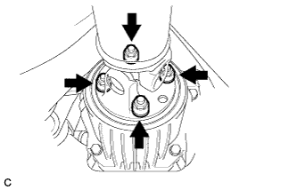
Remove the 4 nuts, 4 bolts and 4 washers.
-
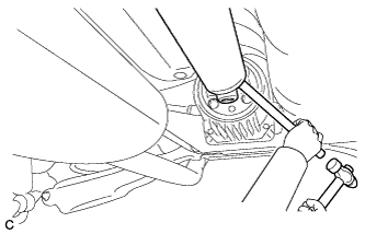
Using a brass bar and a hammer, remove the propeller with center bearing shaft assembly.
-
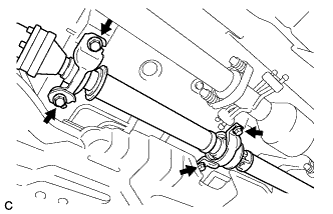
Remove the 4 bolts and 4 No. 2 center support bearing washers.
Note
When removing the bolts and washers, do not apply excessive force to the universal joint.
-
Pull out the propeller with center bearing shaft assembly from the transfer.
Note
-
When removing the propeller shaft, do not apply excessive force to the universal joint.
-
During and after the removal of the propeller shaft, keep the universal joint angle straight (within 15 degrees).
-
Be careful not to damage the oil seal.
-
-
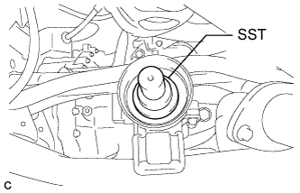
Insert SST into the transfer to prevent oil leakage.
- SST
- 09325-20010
Note
Be careful not to damage the oil seal.
-
-
REMOVE REAR SUSPENSION ARM COVER LH
w/o Air Suspension: Click here
w/ Air Suspension: Click here
-
REMOVE REAR SUSPENSION ARM COVER RH
Tech Tips
Perform the same procedure as the LH side.
-
SEPARATE REAR SPEED SENSOR LH
-
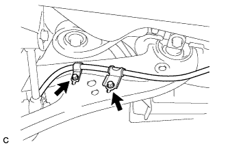
Remove the bolt and separate the rear speed sensor from the rear axle carrier sub-assembly.
Note
-
Prevent foreign matter from attaching to the rear speed sensor tip.
-
Clean the rear speed sensor installation hole and the contact surfaces every time the rear speed sensor is removed.
-
Do not twist or apply excessive force to the rear speed sensor during removal from the rear axle carrier sub-assembly to prevent it from being damaged.
-
-
Remove the bolt and separate the rear speed sensor from the rear trailing arm assembly.
-
-
SEPARATE REAR SPEED SENSOR RH
Tech Tips
Perform the same procedure as the LH side.
-
REMOVE REAR AXLE SHAFT NUT LH
-
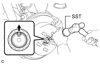
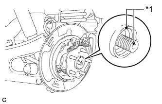
Using SST and a hammer, release the staked part of the rear axle shaft nut.
- SST
- 09930-00010
Note
Loosen the staked part of the nut completely, otherwise the threads of the rear drive shaft assembly may be damaged.
-
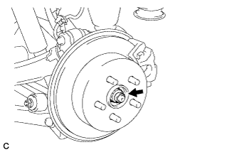
While applying the parking brakes, remove the rear axle shaft nut from the rear drive shaft assembly.
-
-
REMOVE REAR AXLE SHAFT NUT RH
Tech Tips
Perform the same procedure as the LH side.
-
REMOVE REAR DISC BRAKE CALIPER ASSEMBLY LH
-
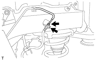
Using a union nut wrench, disconnect the brake line from the rear flexible hose.
Note
-
Do not bend or damage the brake line.
-
Do not allow any foreign matter such as dirt and dust to enter the brake line.
-
-
Remove the clip and separate the rear flexible hose.
-
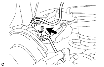
Remove the bolt and separate the rear flexible hose from the rear upper control arm assembly.
-
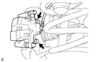
Remove the 2 bolts and rear disc brake caliper assembly with rear flexible hose.
-
-
REMOVE REAR DISC BRAKE CALIPER ASSEMBLY RH
Tech Tips
Perform the same procedure as the LH side.
-
REMOVE PARKING BRAKE SHOE ADJUSTING HOLE PLUG (for LH Side)
-
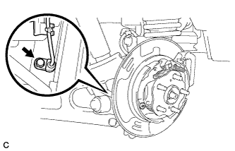
Remove the parking brake shoe adjusting hole plug.
-
-
REMOVE PARKING BRAKE SHOE ADJUSTING HOLE PLUG (for RH Side)
Tech Tips
Perform the same procedure as the LH side.
-
REMOVE REAR DISC LH
-
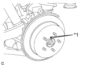
Text in Illustration *1 Matchmark Put matchmarks on the rear disc and the axle hub.
-
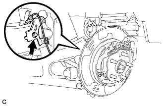
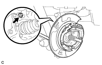
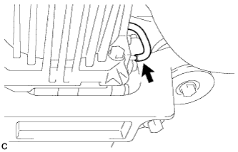
Release the parking brake and remove the rear disc.
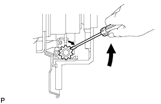
Tech Tips
If the disc can not be removed easily, use a screwdriver to turn the shoe adjuster as shown in the illustration in order to contract the parking brake shoes.
-
-
REMOVE REAR DISC RH
Tech Tips
Perform the same procedure as the LH side.
-
REMOVE REAR AXLE HUB AND BEARING ASSEMBLY LH
-
Text in Illustration *1 Matchmark Put matchmarks on the rear drive shaft assembly and rear axle hub and bearing assembly.
-
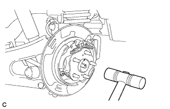
Using a plastic hammer, separate the rear drive shaft assembly from the rear axle hub and bearing assembly.
Tech Tips
If it is difficult to separate, tap the end of the rear drive shaft assembly using a brass bar and a hammer.
-
Remove the 4 bolts and the rear axle hub and bearing assembly from the rear axle carrier sub-assembly.
-
-
REMOVE REAR AXLE HUB AND BEARING ASSEMBLY RH
Tech Tips
Perform the same procedure as the LH side.
-
REMOVE REAR STABILIZER LINK SUB-ASSEMBLY LH
-
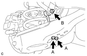
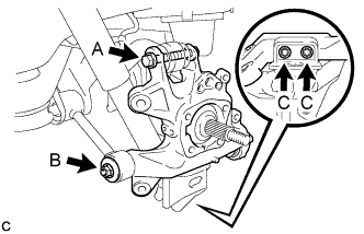
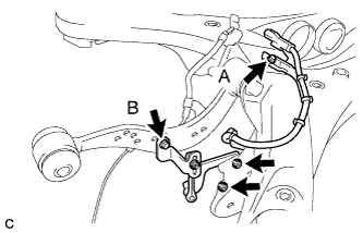
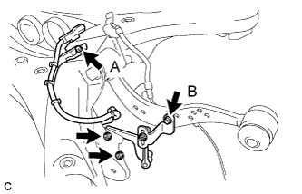
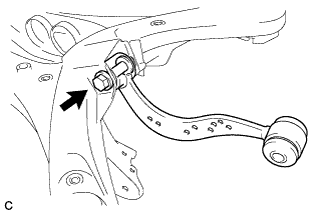
Remove the 2 nuts (A) and rear stabilizer link sub-assembly from the rear No. 2 suspension arm assembly.
-
Remove the nut (B) and separate the rear stabilizer link sub-assembly from the rear stabilizer bar.
Tech Tips
If the ball joint turns together with the nut (B), use a hexagon wrench (6 mm) to hold the stud bolt.
-
-
REMOVE REAR STABILIZER LINK SUB-ASSEMBLY RH
Tech Tips
Perform the same procedure as the LH side.
-
REMOVE REAR STABILIZER BAR
-
Type A:
-
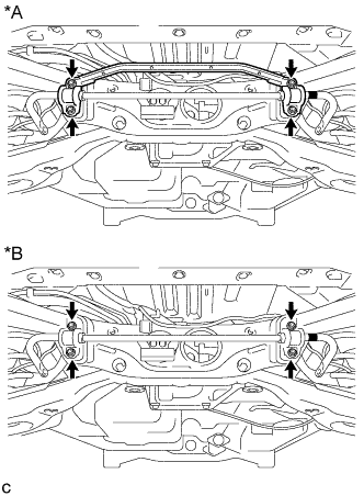
Text in Illustration *A Type A *B Type B Remove the 4 nuts and the rear stabilizer bar with 2 rear stabilizer bushings and rear No. 1 stabilizer bar bracket.
-
-
Type B:
-
Remove the 4 nuts and the rear stabilizer bar with 2 rear stabilizer bushings and 2 rear No. 1 stabilizer bar brackets.
-
-
-
REMOVE REAR PNEUMATIC CYLINDER ABSORBER ASSEMBLY LH (w/ Air Suspension)
-
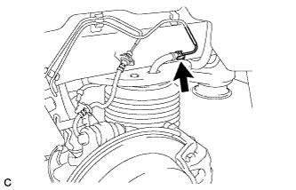
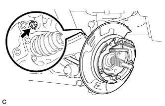
Disconnect the air tube from the rear pneumatic cylinder assembly.
Tech Tips
For the disconnecting procedure of the tube (type 2), refer to Precaution of Suspension Control System Click here.
-
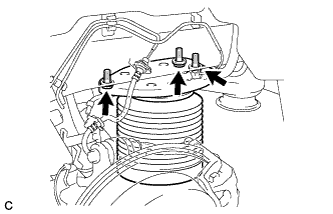
Remove the 3 bolts and separate the rear pneumatic cylinder assembly from the body.
-
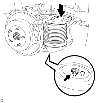
Compress the rear pneumatic cylinder assembly as shown in the illustration.
-
Remove the bolt and rear pneumatic cylinder assembly from the rear No. 2 suspension arm assembly.
Note
-
Hold the lower part of the rear pneumatic cylinder assembly when removing it.
-
Do not extend the rear pneumatic cylinder assembly when removing it.
-
-
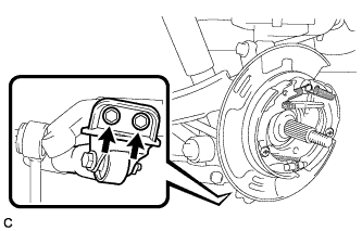
Remove the 2 O-rings, plate and No. 2 connector from the rear pneumatic cylinder assembly.
Note
Perform this procedure when reusing the rear pneumatic cylinder assembly.
Tech Tips
For the removing procedure of the tube (type 2), refer to Precaution of Suspension Control System Click here.
-
-
REMOVE REAR PNEUMATIC CYLINDER ABSORBER ASSEMBLY RH (w/ Air Suspension)
Tech Tips
Perform the same procedure as the LH side.
-
LOOSEN REAR LOWER SHOCK ABSORBER BRACKET SUB-ASSEMBLY LH
-
Loosen the 2 bolts to remove the rear axle carrier sub-assembly LH after removing the rear trailing arm assembly LH.
CAUTION:
Do not remove the bolts.
-
-
LOOSEN REAR LOWER SHOCK ABSORBER BRACKET SUB-ASSEMBLY RH
Tech Tips
Perform the same procedure as the LH side.
-
REMOVE REAR NO. 2 SUSPENSION ARM ASSEMBLY LH
w/o Air Suspension: Click here
w/ Air Suspension: Click here
-
REMOVE REAR NO. 2 SUSPENSION ARM ASSEMBLY RH
Tech Tips
Perform the same procedure as the LH side.
-
LOOSEN PARKING BRAKE ASSEMBLY LH
-
Loosen the nut to separate the parking brake assembly after removing the rear trailing arm assembly.
-
-
LOOSEN PARKING BRAKE ASSEMBLY RH
Tech Tips
Perform the same procedure as the LH side.
-
REMOVE REAR TRAILING ARM ASSEMBLY LH
-
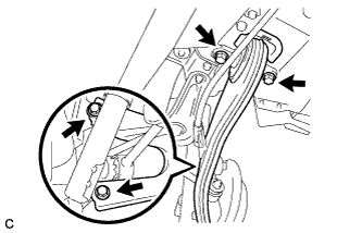
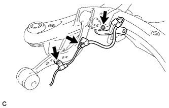
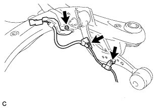
Remove the 2 bolts and separate the No. 3 parking brake cable assembly from the rear trailing arm assembly.
-
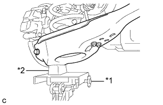
Text in Illustration *1 Jack *2 Wooden Block Using a jack and wooden block, jack up the rear No. 2 suspension arm assembly to replicate standard vehicle height conditions.
CAUTION:
Do not jack up the rear No. 2 suspension arm assembly too high as the vehicle may fall.
-
Remove the 4 bolts, 2 washers and rear trailing arm assembly.
-
Slowly lower the rear No. 2 suspension arm assembly.
-
-
REMOVE REAR TRAILING ARM ASSEMBLY RH
Tech Tips
Perform the same procedure as the LH side.
-
SEPARATE PARKING BRAKE ASSEMBLY LH
-
Remove the nut and separate the parking brake assembly from the rear axle carrier sub-assembly.
Note
Use wire or an equivalent tool to keep the parking brake assembly from hanging down by the parking brake cable.
-
-
SEPARATE PARKING BRAKE ASSEMBLY RH
Tech Tips
Perform the same procedure as the LH side.
-
REMOVE REAR AXLE CARRIER SUB-ASSEMBLY LH
-
Remove the bolt (A) and nut, and then separate the rear upper control arm assembly LH from the rear axle carrier sub-assembly LH.
Note
Since the stopper nut is used, loosen the bolt (A).
-
Remove the nut (B), spacer, 2 bolts (C) and rear axle carrier sub-assembly LH.
Note
-
Be careful not to damage the rear drive shaft outboard joint boot.
-
Use wire or an equivalent tool to keep the rear drive shaft assembly from hanging down.
-
-
-
REMOVE REAR AXLE CARRIER SUB-ASSEMBLY RH
Tech Tips
Perform the same procedure as the LH side.
-
REMOVE REAR DRIVE SHAFT ASSEMBLY LH
-
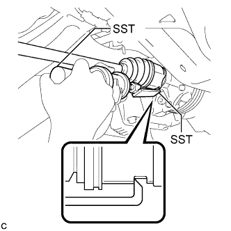
Using SST, remove the rear drive shaft assembly as shown in the illustration.
- SST
- 09520-00031
- 09520-01010
Note
When removing the rear drive shaft assembly, keep it level.
-
-
REMOVE REAR DRIVE SHAFT ASSEMBLY RH
Tech Tips
Perform the same procedure as the LH side.
-
REMOVE REAR DRIVE SHAFT SNAP RING LH
-
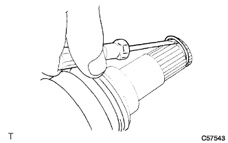
Using a screwdriver, remove the rear drive shaft snap ring.
-
-
REMOVE REAR DRIVE SHAFT SNAP RING RH
Tech Tips
Perform the same procedure as the LH side.
-
REMOVE REAR DIFFERENTIAL CARRIER ASSEMBLY WITH DIFFERENTIAL SUPPORT
-
Disconnect the vacuum hose from the electro magnetic control coupling sub-assembly.
-
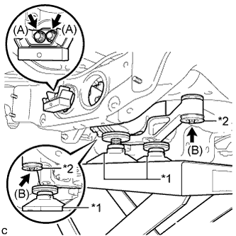
Text in Illustration *1 Attachment *2 Lower Rear Differential Mount Stopper Support the rear differential carrier assembly with differential support with a jack using 3 attachments as shown in the illustration.
-
Remove the 2 bolts (A) and rear differential dynamic damper from the differential support.
-
Remove the 2 bolts (B), 2 nuts and 2 lower rear differential mount stoppers from the No. 1 rear differential support.
Tech Tips
The nuts have tabs to prevent them from rotating.
-
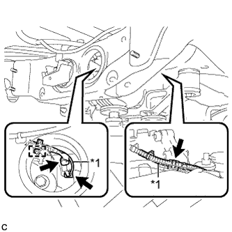
Text in Illustration *1 Vacuum Hose Slightly lower the rear differential carrier assembly with differential support, remove the vacuum hose from the 2 clamps, disconnect the connector, and remove the clamp from the connector bracket.
-
Lower the rear differential carrier assembly with differential support slowly to remove the rear differential carrier assembly with differential support.
Note
Do not damage the vacuum hose and electro magnetic control coupling wire harness.
-
-
REMOVE FRAME WIRE
-
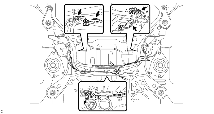
Remove the bolt and disconnect the connectors, and then disengage the clamps to separate the frame wire from rear suspension member as shown in the illustration.
Tech Tips
There are only the connector (A) and the clamp (A) on vehicles with the air suspension.
-
-
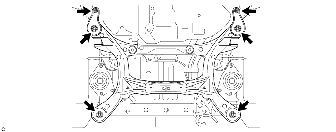
REMOVE REAR SUSPENSION MEMBER SUB-ASSEMBLY
-
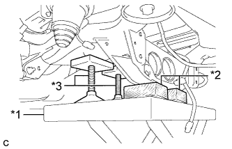
Text in Illustration *1 Jack *2 Wooden Block *3 Attachment Support the rear suspension member with a jack using 2 wooden blocks and 2 attachments or equivalent tools as shown in the illustration.
Note
Make sure to secure the rear suspension member to prevent it from dropping.
-
Remove the 2 nuts, 4 bolts, 2 rear lower suspension braces and 2 rear lower suspension member stoppers.
-
Slowly lower the rear suspension member.
Note
When lowering the rear suspension member, be careful not to damage the vehicle body or other components installed on the vehicle.
-
-
REMOVE REAR NO. 1 SUSPENSION ARM ASSEMBLY LH
-
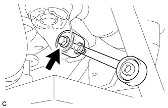
Remove the bolt, nut and rear No. 1 suspension arm assembly LH from the rear suspension member sub-assembly.
Note
Since the stopper nut is used, loosen the bolt.
-
-
REMOVE REAR NO. 1 SUSPENSION ARM ASSEMBLY RH
Tech Tips
Perform the same procedure as the LH side.
-
REMOVE REAR SUSPENSION MEMBER UPPER STOPPER
-
Remove the 2 rear suspension member upper stoppers.
-
-
REMOVE REAR SUSPENSION MEMBER REAR UPPER STOPPER
-
Remove the 2 rear suspension member rear upper stoppers.
-
-
REMOVE REAR HEIGHT CONTROL SENSOR SUB-ASSEMBLY RH
-
Remove the bolt (B) and separate the rear height control sensor sub-assembly RH from the rear upper control arm assembly RH.
-
Remove the bolt (A), 2 nuts and rear height control sensor sub-assembly RH from the rear suspension member sub-assembly.
-
-
REMOVE REAR HEIGHT CONTROL SENSOR SUB-ASSEMBLY LH (w/ Air Suspension)
-
Remove the bolt (B) and separate the rear height control sensor sub-assembly LH from the rear upper control arm assembly LH.
-
Remove the bolt (A), 2 nuts and rear height control sensor sub-assembly LH from the rear suspension member sub-assembly.
-
-
REMOVE REAR SPEED SENSOR LH
-
Remove the 2 bolts, nut and rear speed sensor LH.
-
-
REMOVE REAR SPEED SENSOR RH
-
Remove the 2 bolts, nut and rear speed sensor RH.
-
-
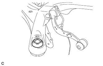
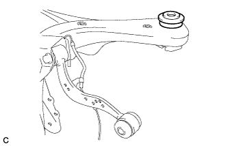
REMOVE REAR UPPER CONTROL ARM ASSEMBLY LH
-
Remove the bolt, nut and rear upper control arm assembly LH from the rear suspension member sub-assembly.
Note
Since the stopper nut is used, loosen the bolt.
-
-
REMOVE REAR UPPER CONTROL ARM ASSEMBLY RH
Tech Tips
Perform the same procedure as the LH side.
-
REMOVE REAR DIFFERENTIAL MOUNT CUSHION
-
Using SST, remove the rear differential mount cushion.
- SST
- 09570-48010
Note
-
Apply grease to the threads of the SST bolts before use.
-
Do not set SST in the wrong direction.
-
Be sure to use SST in the correct combination.
-
Do not bring SST into contact with the rear suspension member.
-
Do not slant the SST bolts.
-
Tighten the 2 SST bolts equally into the 2 rear differential mount cushion holes.
-
-
REMOVE REAR SUSPENSION MEMBER FRONT BODY MOUNTING CUSHION (for LH Side)
-
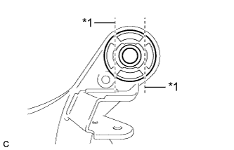
Text in Illustration *1 Bend Portion Using a chisel and hammer, bend the 2 portions of the rear suspension member front body mounting cushion rib.
Note
Make sure to bend the 2 portions of the cushion rib until the claws of SST can fit securely.
-
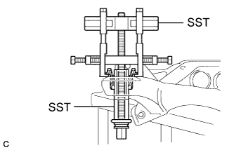
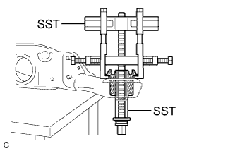
Install SST as shown in the illustration.
- SST
- 09830-10010 ( 09830-01010, 09830-01040, 09830-01050 )
- 09950-40011 ( 09951-04020, 09952-04010, 09954-04010, 09955-04051, 09958-04011 )
Note
Apply a small amount of grease to the threads and tip of SST (center bolt) before use.
-
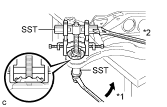
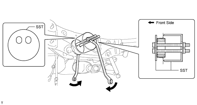
Text in Illustration *1 Turn *2 Hold Using SST, separate the rear suspension member front body mounting cushion (LH Side) from the rear suspension member sub-assembly, while applying grease to the clearance between the rear suspension member front body mounting cushion (LH Side) and the rear suspension member sub-assembly.
- SST
- 09830-10010 ( 09830-01010, 09830-01040, 09830-01050 )
- 09950-40011 ( 09951-04020, 09952-04010, 09954-04010, 09955-04051, 09958-04011 )
Note
-
Set the claws of SST onto the rear suspension member sub-assembly securely as shown in the illustration.
-
Be careful as the rear suspension member front body mounting cushion may fly out.
-
The rear suspension member front body mounting cushion cannot be reused.
-
Remove SST and the rear suspension member front body mounting cushion (LH Side) from the rear suspension member sub-assembly.
-
-
REMOVE REAR SUSPENSION MEMBER FRONT BODY MOUNTING CUSHION (for RH Side)
Tech Tips
Perform the same procedure as the LH side.
-
REMOVE REAR SUSPENSION MEMBER REAR BODY MOUNT CUSHION LH
-
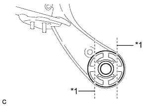
Text in Illustration *1 Bend Portion Using a chisel and hammer, bend the 2 portions of the rear suspension member rear body mounting cushion LH rib.
Note
Make sure to bend the 2 portions of the cushion rib until the claws of SST can fit securely.
-
Install SST as shown in the illustration.
- SST
- 09830-10010 ( 09830-01010, 09830-01040, 09830-01050 )
- 09950-40011 ( 09951-04020, 09952-04010, 09954-04010, 09955-04051, 09958-04011 )
Note
Apply a small amount of grease to the threads and tip of SST (center bolt) before use.
-
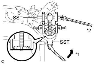
Text in Illustration *1 Turn *2 Hold Using SST, separate the rear suspension member rear body mounting cushion LH from the rear suspension member sub-assembly, while applying grease to the clearance between the rear suspension member rear body mounting cushion LH and the rear suspension member sub-assembly.
- SST
- 09830-10010 ( 09830-01010, 09830-01040, 09830-01050 )
- 09950-40011 ( 09951-04020, 09952-04010, 09954-04010, 09955-04051, 09958-04011 )
Note
-
Set the claws of SST onto the rear suspension member sub-assembly securely as shown in the illustration.
-
Be careful as the rear suspension member rear body mounting cushion may fly out.
-
The rear suspension member rear body mounting cushion cannot be reused.
-
Remove SST and the rear suspension member rear body mounting cushion LH from the rear suspension member sub-assembly.
-
-
REMOVE REAR SUSPENSION MEMBER REAR BODY MOUNT CUSHION RH
Tech Tips
Perform the same procedure as the LH side.
-
REMOVE HOLE PLUG
-
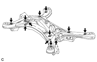
Remove the 12 hole plugs from the rear suspension member as shown in the illustration.
-